Key takeaways
- Provide the moving load and its geometry, not mass alone.
- Define process timing without prescribing unsupported settings.
- Evaluate stopping and settling within the complete fixture review.
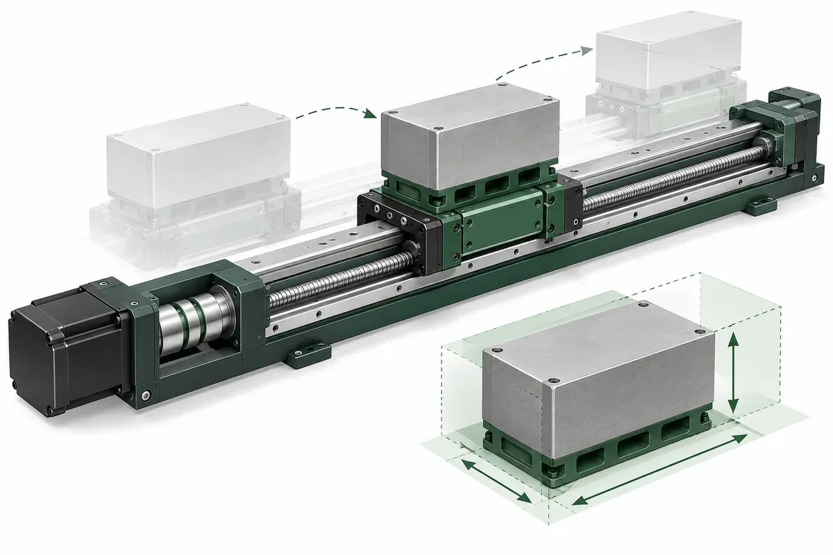
A requested cycle time is a useful design input; an acceleration value copied from another machine is usually not. The loaded axis includes the payload, adapters, moving services and other components that the drive must accelerate or decelerate. Prepare that information before asking an integrator to select and verify the motion profile.
Describe the moving assembly
List everything that moves with the axis and show its location relative to the supporting structure. Include fixture mass, specimen variations, center-of-mass offsets and attached cables or hoses. For rotary movement, provide the geometry needed to assess inertia rather than giving total mass as if it fully described the load.
Record orientation and the sequence of positions used during the process. A stacked assembly can present different loading conditions to different axes. The supporting axis may carry both the specimen and the upper mechanism, while the upper axis carries only part of that assembly.
Mark uncertain inputs for confirmation. Do not turn a horizontal catalogue payload into a vertical operating rating or infer an acceleration capability from a static load number. The specification guide explains why unsupported conditions remain unconfirmed.
Give the process requirement before the setting
Describe the required displacement, available cycle time, acquisition window and acceptable disturbance at the process point. Identify whether the process acts during movement or only afterward. These inputs let the integration provider evaluate a profile against the actual objective.
The Zaber velocity study reports dynamic evaluation under defined test conditions. It supports the need to state conditions when interpreting motion performance. Its numerical settings and results are not recommendations for another stage or load.
Ask for a documented basis for the proposed profile, including any relevant restrictions. A maximum speed value alone does not establish how quickly that speed can be reached, whether the required move is long enough to reach it, or how long the fixture needs before measurement.
Loaded-axis input checklist
- Itemize the full moving mass and the expected specimen range.
- Provide center-of-mass location, rotary geometry and mounting orientation.
- Show cable and hose routing through the intended movement.
- State move distances, repetitions and process timing requirements.
- Define the measurement or disturbance criterion after deceleration.
- Request a reviewed profile and its applicable load conditions.
- Include stopping behavior and protective measures in the qualified machine review.
Keep numerical operating settings out of the requirements until the responsible provider has evaluated the configuration. Do not increase current, acceleration or limit values merely to make a demonstration meet the desired cycle time.
Hypothetical heavier-camera change
Consider an imaginary fixture initially evaluated with a compact camera. A later revision adds a heavier optical assembly farther from the carriage support. The nominal travel and inspection positions remain unchanged, but the load distribution and disturbance behavior may differ.
The project should reopen the profile review and measurement readiness test rather than copying the previous settings without evaluation. The integrator receives the revised mass properties, bracket drawing and cycle requirement. If the original throughput cannot be maintained within the approved operating envelope, the team considers mechanical or process changes instead of treating more aggressive tuning as the default answer.
No acceleration value is assigned in this example. The point is that a payload revision can change the evidence needed even when the recipe coordinates are identical.
Accept the result under representative conditions
Plan a controlled test that covers the relevant load and operating cases. Record whether the process requirement is met, how readiness is determined and whether the behavior remains consistent over the intended sequence. Include environmental and mounting conditions that materially affect the interpretation.
Separate normal process deceleration from emergency or protective stopping functions. Their design and verification belong to the qualified machine-level safety assessment and equipment instructions. A successful ordinary move does not establish protective stopping performance.
Save the accepted profile configuration with the fixture revision and test record. Revisit it after changes to payload, orientation, services, mechanism or controller configuration. That preserves the useful result: a documented relationship between a specific loaded assembly and its demonstrated process performance.
Questions
Is payload mass enough to select acceleration?
No. Geometry, offsets, orientation, moving services and process behavior also matter.
Can catalogue maximum speed determine cycle time?
Not alone. The motion profile, move length, settling and acquisition overhead also affect the cycle.
Should a heavier payload use the old settings?
Only after the responsible engineering review establishes that the previous configuration remains appropriate.
Sources & scope
Sources support the specific points described below. General engineering guidance and third-party examples do not establish a catalogue model's performance or suitability.
- Zaber: Velocity stability and following error
Only dynamic evaluation under stated test conditions; the loaded-axis worksheet contains original requirements guidance.
Accessed
Related engineering resources
Continue reading
Motion Control & Automation
Absolute and relative moves in a repeatable work sequence
Choose absolute and relative move semantics, document units and references, and prevent duplicate execution during communication recovery.
Integration guide · 4 min read ·Motion Control & Automation
Choosing move-and-settle or continuous-scan operation
Compare stationary acquisition with continuous scanning by separating settling, dynamic motion, synchronization and throughput evidence.
Integration guide · 4 min read ·From requirements to a quotation
Review your stage requirements
Share the motion envelope, payload, orientation and acceptance criteria. Request confirmation of the exact configuration before ordering.
Request a Quote