Key takeaways
- Identify exactly where a feedback sensor measures.
- Separate feedback used for monitoring from feedback used for control.
- Validate the process point even when an encoder is present.
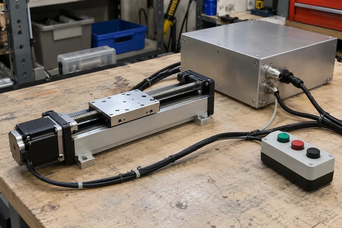
“Encoder feedback” is an incomplete description of a positioning system. The sensor may observe a motor shaft, a carriage or another mechanical element, while the process depends on a feature farther along the load path. Before comparing feedback options, draw that path and identify what each proposed measurement can actually establish.
Draw the measurement chain
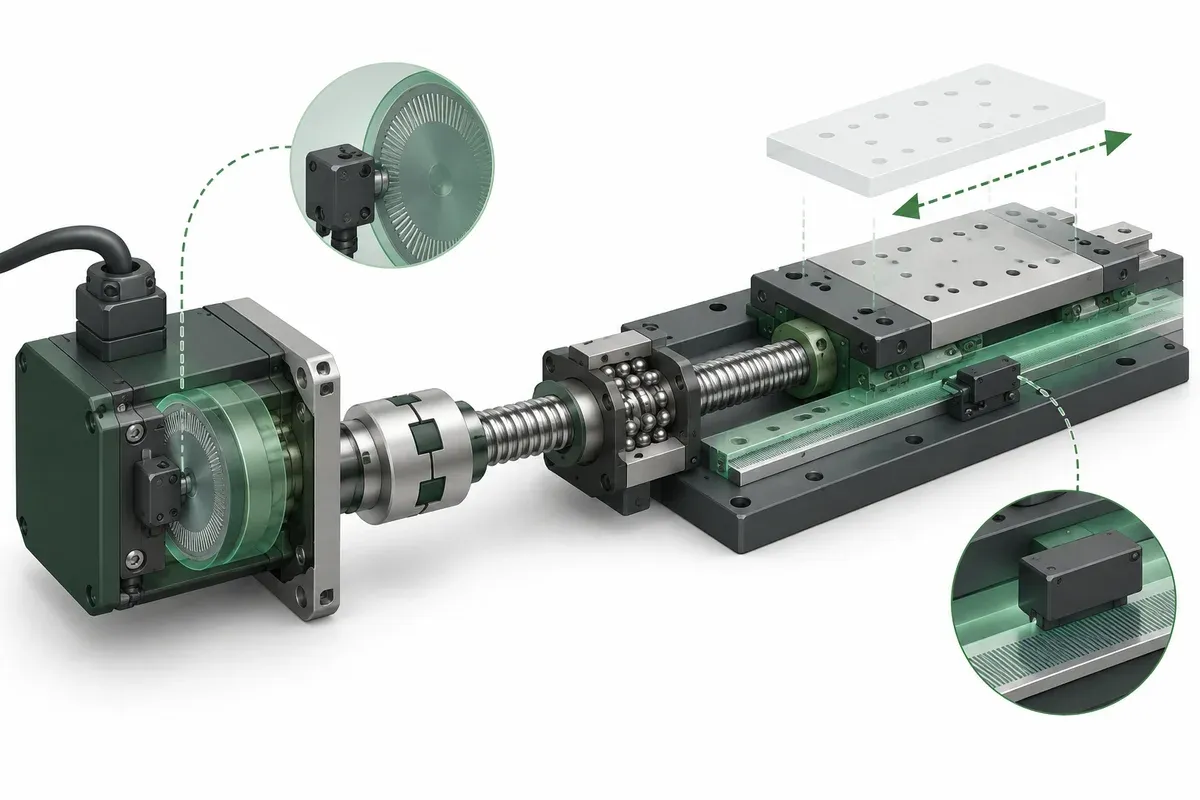
Begin with the motor, transmission, carriage, adapter, fixture and workpiece. Put the sensor and its reference structure on the drawing. A motor-mounted rotary encoder measures rotation at the motor; translating that measurement into workpiece location requires a justified mechanical relationship. A stage-position sensor observes a different point in the chain, but still may not observe fixture deformation or movement of the specimen within its holder.
The PI linear-stage overview distinguishes linear-encoder and motor-encoder arrangements. That source describes PI offerings and is not evidence of encoder availability or compatibility for this catalogue. For any shortlisted stage, request its exact sensor location, function and configuration from the supplier.
Do not replace the drawing with a label such as “fully closed loop.” The drawing makes residual unobserved elements visible and gives reviewers a concrete basis for questions.
Ask how feedback is used
A sensor may supply a readout, a fault-monitoring signal or input to a control loop. Ask which role applies and where processing occurs. Also identify whether the reported position represents the measured value, the commanded trajectory or a derived estimate. Similar field names across controllers can conceal different meanings.
Request the supported feedback interfaces and the approved controller configuration. A connector or encoder brand alone does not establish electrical or software compatibility. The integration provider should document scaling, direction, reference behavior and what happens if the signal becomes invalid.
Keep the performance requirement independent of the proposed architecture. If the process needs a particular location at the workpiece, specify that outcome and its measurement method. Let the supplier explain how the offered feedback arrangement supports it, including what remains outside the observed chain.
Feedback-location review checklist
- Mark the sensor, moving target and reference structure on a mechanical diagram.
- Identify every coupling, transmission and fixture element between sensor and process point.
- State whether feedback is used for display, monitoring, control or a documented combination.
- Define the meaning and units of every position field the host receives.
- Request exact feedback-interface compatibility and signal-loss behavior.
- Assign an independent workpiece verification method and uncertainty budget.
- Record which changes require the feedback relationship to be reviewed again.
Use the checklist for both apparently simple single axes and stacked assemblies. An additional axis can move the measurement point or change the load path without changing the label on the encoder.
Hypothetical flexible-fixture comparison
Consider an imaginary inspection stage with a long bracket carrying a target. Option A observes motor rotation; option B observes carriage displacement. If the bracket flexes while the carriage remains in place, neither observation directly establishes the target’s final location.
The engineering team therefore specifies a target-level verification experiment and reviews whether the bracket should be redesigned. It does not assume that choosing option B alone will remove every source of process error. Conversely, it does not dismiss carriage feedback merely because some errors remain unobserved; it asks what specific uncertainty each arrangement reduces.
This example is architectural reasoning, not a performance comparison between catalogue models. No numeric accuracy improvement is assigned to either option without test evidence.
Report performance at a named point
The final acceptance statement should name the measurement location, reference, payload, operating condition and test method. Include the feedback arrangement as configuration information rather than substituting it for the result. “Encoder installed” is not a metrology conclusion.
The specification guide helps distinguish resolution, repeatability and accuracy. Apply those terms to the point actually tested. Where the measurement does not reach the workpiece, explain the remaining relationship and its uncertainty. That makes the result useful to the next engineer instead of leaving them to infer what the feedback label meant.
A useful review drawing also identifies the mounting surface used as the sensor reference, because movement of that reference can change the interpretation of the feedback.
Questions
Does a motor encoder measure carriage position directly?
It measures motor rotation. The relationship to carriage and workpiece position depends on the intervening mechanism.
Does carriage feedback observe fixture deflection?
Not necessarily. Identify whether the deflecting element lies beyond the measured point.
Can feedback be present without controlling position?
Yes. Confirm whether it is used for monitoring, display or a documented control loop.
Sources & scope
Sources support the specific points described below. General engineering guidance and third-party examples do not establish a catalogue model's performance or suitability.
- PI: Precision motorized linear stages
Only the distinction between linear-encoder and motor-encoder arrangements in PI offerings; no catalogue option or performance is inferred.
Accessed
Related engineering resources
Continue reading
Motion Control & Automation
Absolute and relative moves in a repeatable work sequence
Choose absolute and relative move semantics, document units and references, and prevent duplicate execution during communication recovery.
Integration guide · 4 min read ·Motion Control & Automation
Acceleration and deceleration requirements for a loaded axis
Prepare load-specific acceleration and deceleration requirements without copying tuning values from an unloaded stage demonstration.
Integration guide · 4 min read ·From requirements to a quotation
Review your stage requirements
Share the motion envelope, payload, orientation and acceptance criteria. Request confirmation of the exact configuration before ordering.
Request a Quote