Key takeaways
- Software travel limits depend on a valid coordinate context.
- A physical switch is not automatically a safety-rated function.
- Review the payload and services as part of the travel envelope.
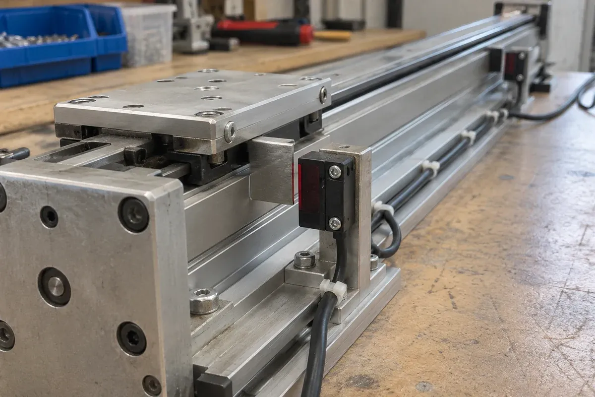
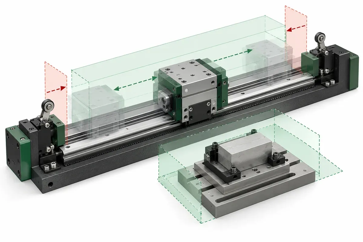
The end of a catalogue travel range, a configured software boundary and a physical limit switch are different pieces of information. A fixture review should identify all three without treating any one of them as complete protection against collisions. The goal is a documented limit map that a qualified integrator can evaluate alongside the machine’s protective measures.
Build a map before discussing settings
Start with the stage drawing, payload drawing and the complete arrangement of cables, hoses and neighboring equipment. Show the required work positions and the surrounding swept envelope. A carriage may remain within its nominal travel while a tall payload contacts an overhead instrument or a cable reaches its routing constraint.
Add the documented reference location, any physical limit sensors, and the proposed operating region as distinct annotations. Keep uncertain locations visibly unresolved. Do not substitute an assumed sensor offset or a remembered value from another stage model.
The Zaber protocol manual documents software travel bounds for its products. That reference demonstrates the need for explicit definitions; it does not establish which limit functions or settings exist for the controller selected for this catalogue.
Describe what each boundary is meant to do
A software travel limit constrains commanded movement within a coordinate framework. Its usefulness therefore depends on the correct coordinate state, units and configuration. Ask what happens before referencing, after a configuration change and when communication is interrupted. Require the controller provider to document these cases rather than predicting them from a user-interface label.
A physical switch provides a signal at a physical location, but the system response depends on its wiring and the receiving electronics. Record whether a signal is used for referencing, operational travel limitation or another documented purpose. An ordinary switch and application program should not be described as a certified protective function without the relevant system evidence.
Keep mechanical stops distinct as well. A stop’s presence is not permission to use impact as a normal positioning method. Obtain the approved operating instructions for the complete machine and preserve all limits and interlocks during evaluation.
Limit-review checklist
- Identify the nominal travel source and its revision for each axis.
- Show the payload, fixture and service-routing envelope at relevant positions.
- Mark sensor locations only from current drawings or verified observations.
- Record the coordinate basis and ownership of proposed software boundaries.
- Ask for documented behavior when a limit signal or reference becomes invalid.
- Assign a qualified reviewer to evaluate protective functions and stopping requirements.
- Define a controlled verification method without bypassing switches or interlocks.
Record the evidence behind every boundary. “Limit fitted” is not a sufficient description because it leaves both the location and the expected reaction ambiguous. Include how configuration changes will be checked and approved before the fixture returns to service.
Hypothetical overhanging-payload review
Consider an imaginary translation fixture carrying a camera bracket. The stage’s full travel is mechanically available, but the bracket approaches a neighboring enclosure before the carriage reaches the end of that travel. A reviewer notices this conflict in the assembly model, before any motion test.
The team revises the fixture layout and defines a smaller proposed work region for evaluation. It then requests the controller’s documented limit behavior and a qualified assessment of the remaining hazards. No numerical limit setting is inferred from the catalogue. The example illustrates why a stage-only drawing cannot establish machine-level clearance.
If the bracket is later replaced with a larger version, the old map must be reviewed again. Copying the previous configuration is insufficient evidence that the new arrangement is acceptable.
Keep verification and change control together
The acceptance plan should identify the observations that demonstrate the intended boundary behavior under an approved test procedure. It should also identify which outcomes stop the test and require engineering investigation. Do not create faults by defeating protective devices or deliberately driving into an obstruction.
Keep the released limit map with the fixture revision, controller configuration and risk-review record. The specification guide explains why missing catalogue fields remain unconfirmed. Apply the same discipline here: an undocumented safety or control behavior remains unresolved until supported by the selected system’s evidence.
Questions
Can software limits replace a risk assessment?
No. Their function and failure behavior must be evaluated within the complete machine design.
Does a physical limit switch prove a safety rating?
No. A rating requires evidence for the relevant function and complete implementation, not merely the presence of a switch.
Why review limits after a payload change?
The new payload and its services can change the collision envelope even when stage travel is unchanged.
Sources & scope
Sources support the specific points described below. General engineering guidance and third-party examples do not establish a catalogue model's performance or suitability.
- Zaber ASCII Protocol Manual
Only the existence of documented software travel bounds for Zaber devices; no compatibility or safety certification is inferred.
Accessed
Related engineering resources
Continue reading
Motion Control & Automation
Absolute and relative moves in a repeatable work sequence
Choose absolute and relative move semantics, document units and references, and prevent duplicate execution during communication recovery.
Integration guide · 4 min read ·Motion Control & Automation
Acceleration and deceleration requirements for a loaded axis
Prepare load-specific acceleration and deceleration requirements without copying tuning values from an unloaded stage demonstration.
Integration guide · 4 min read ·From requirements to a quotation
Review your stage requirements
Share the motion envelope, payload, orientation and acceptance criteria. Request confirmation of the exact configuration before ordering.
Request a Quote