Key takeaways
- Identify motor, power drive, motion controller and feedback roles separately.
- Calculate nominal command increments from the documented scale and verify physical movement independently.
- Record the direction, electrical interpretation and validity of each signal.
- An absolute encoder value still needs a valid relationship to the machine and workpiece reference.
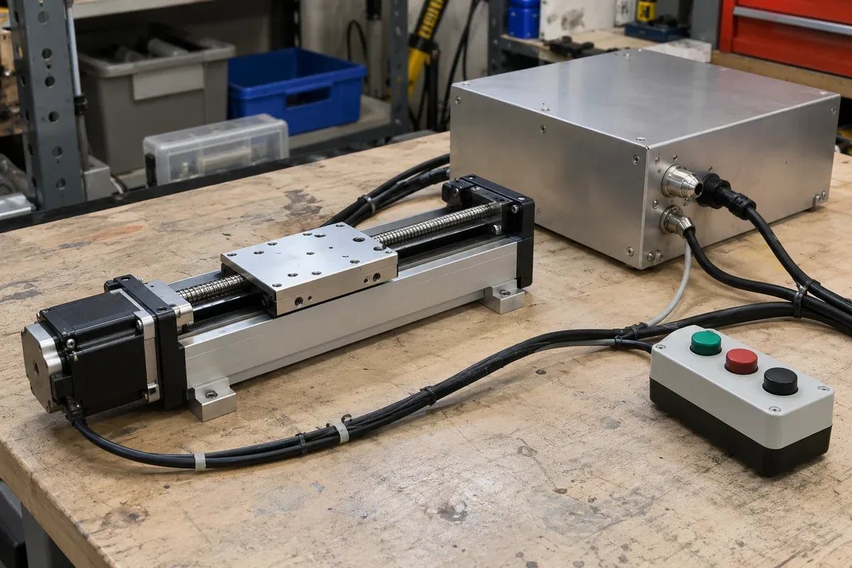
A motion quotation can use motor, drive and controller as if they described one box. An integration record needs their functions separated, even when one product contains several functions. Follow the command, electrical energy and measurement through the proposed system before interpreting a step count or position value.
This reference explains terminology for stage selection and integration. Its examples provide no catalogue motor angle, electrical rating, pin assignment, supported interface or restart procedure.
Follow the command and energy paths
Motion control is the controlled manipulation of mechanical movement. The application defines the requested action; control and power hardware make the mechanism respond. A useful functional description identifies these roles:
| Term | Function to identify |
|---|---|
| Motion controller | Interprets motion requests and generates or coordinates the commands needed for the intended trajectory or sequence. |
| Drive or amplifier | Converts controller commands into controlled electrical power for the motor. Its current-control and other loop functions depend on the design. |
| Motor | Converts electrical energy into mechanical force or torque. The transmission and guidance determine how that becomes platform movement. |
| Feedback sensor | Reports a measured quantity at a particular location for control, monitoring or display. |
ADVANCED Motion Controls describes this functional chain and the overlap between modern drives and controllers. A combined enclosure does not remove the need to identify each responsibility.
The word driver also appears in host software. A device driver or communication library helps a computer interact with hardware; it is distinct from the motor power drive. Record which meaning the document uses and the relevant hardware, firmware and software versions.
Understand servo, stepper and brushless labels
A servo system uses feedback to regulate a controlled variable, commonly position, velocity or torque. In a position-servo example, a requested position is compared with measured position; the control system acts on the error through the drive and motor, then receives updated measurements. A servo drive, also called a servo amplifier, supplies motor power in response to the relevant command. The allocation of position, velocity and current loops varies between products.
A stepper motor advances incrementally as its driver sequences winding currents. In a rotary stepper, the rotor responds to the changing magnetic excitation. Full-step operation advances between specified step positions; microstepping uses intermediate current combinations to subdivide the commanded increment. Dover Motion’s explanation describes this operating principle. It does not establish the step angle of a catalogue stage motor.
Brushless describes construction and commutation. In the BLDC example described by Texas Instruments, an electronic drive commutates winding current using rotor-position information or a sensorless method. Brushless commutation alone does not mean that an external positioning loop measures the workpiece.
Conventional stepper motors of the winding-sequenced kind discussed here also have brushless construction: commutation is handled electronically, without a brush/commutator assembly. AMCI describes this construction. In commercial comparisons, “brushless motor” often refers more specifically to a BLDC or permanent-magnet synchronous motor (PMSM) product/drive family. Identify that specific architecture instead of treating “brushless” and “stepper” as mutually exclusive construction categories.
These labels answer different questions. A brushless motor can serve in a servo system, and stepper systems can also use feedback. For a brushless-versus-stepper comparison, identify the actual motor, drive, command method and feedback arrangement. For a servo proposal, identify what variable is regulated and where it is measured. A motor label cannot establish the complete system’s accuracy or supported interface.
A counted-step arrangement can make incremental sequencing and nominal conversion straightforward without a position-feedback channel. Its commands still require physical verification. A feedback arrangement can react to its measured error, while fixture movement beyond the sensor remains unobserved. Compare these benefits and limits against the task rather than declaring one label universally preferable.
Convert full steps into nominal stage travel
A full-step angle is the specified motor-shaft rotation associated with a full step. If that angle is alpha degrees, the nominal full-step count per motor revolution is:
N = 360 / alpha
Let u be the commanded subdivisions per full step, r the number of motor revolutions per screw revolution, and L the screw’s axial travel per revolution, or lead. With a documented fixed transmission and one command count per subdivision:
Nominal travel per count = L / (N × u × r)
Use the specified lead and transmission convention. A thread-pitch label or an inverted gear ratio can produce the wrong scale. Zaber’s protocol manual illustrates why physical-unit conversions are device- and configuration-specific.
For a hypothetical calculation, choose alpha = 1.8 degrees, u = 8, r = 2 and L = 4 mm. These invented inputs give N = 200 and 3,200 command counts per screw revolution. The nominal travel is 4 / 3,200 = 0.00125 mm, or 1.25 micrometres per count. A nominal 10-micrometre request therefore corresponds to eight counts under those assumptions.
This is command resolution. It does not establish minimum incremental motion, accuracy or equal physical movement for each microstep. Check whether an API already accepts engineering units before applying a second conversion. Preserve the actual subdivision, transmission and unit definitions with the recipe; use independent measurements for the displacement that matters.
Read speed, torque and electrical ratings at their boundary
If a driver receives f command counts per second under the subdivision convention above, the nominal motor-shaft speed is 60f / (N × u) revolutions per minute. Screw speed also depends on r. This conversion describes a command rate; it does not establish that a loaded motor follows it or identify a universal maximum RPM.
A speed-torque curve relates available torque to shaft speed for a stated motor/driver configuration. Oriental Motor identifies supply, driver, winding connection, step mode and test-load conditions as relevant curve information. Starting, accelerating and running are distinct cases. Read the appropriate documented operating region instead of treating a no-load speed as loaded-axis capability.
Holding torque concerns an energized motor at rest under stated conditions. It is distinct from available running torque, a mechanical brake and verified load holding after power loss. The stage’s permitted load also involves its mechanism, orientation and fixture geometry.
Voltage, measured in volts, is an electrical potential difference; current, measured in amperes, is charge flow. A drive’s input-supply requirement, motor winding data and phase-current setting describe different boundaries. Preserve the manufacturer’s peak/RMS, per-phase, continuous/peak and connection conventions. Do not substitute a supply-current number for a winding-current setting or infer a permitted driver supply from a motor label.
Distinguish motion ramps from torque removal
An acceleration ramp is the time-dependent change from one commanded velocity to another. With constant acceleration, velocity varies linearly with time; the acceleration, cruise and deceleration phases can form a trapezoid on a velocity–time plot. Jerk is the rate of change of acceleration. A jerk-shaped or S-curve profile changes acceleration during transitions rather than imposing an ideal instantaneous acceleration jump, as Kollmorgen’s profile reference illustrates. Profile names describe the command shape, not verified load response or settling. Actual permitted limits remain configuration-specific; no parameter values or commissioning procedure are given here.
Safe Torque Off (STO) is a drive safety function intended to inhibit torque-producing energy to the motor. It differs from an ordinary commanded stop, which may use powered deceleration: STO alone does not supply controlled braking, engage a holding brake or provide electrical isolation. Rockwell’s current STO manual describes coasting and warns that external forces can still move a load and dangerous voltages can remain. A normal stop or zero-speed indication does not establish STO or safe isolation. No STO capability or safety rating is claimed for any catalogue stage/control package. Its actual safety functions need equipment-specific assessment and validation; this reference provides no STO wiring or safety implementation.
Treat phases and wire colours as configuration information
A motor phase is a winding or winding group driven according to the motor design. Phase count and external lead count are different descriptions: winding connections and available taps affect the wiring arrangement. Use the exact motor and driver connection documentation.
A colour identifies a conductor within an identified harness or drawing. Reusing that colour-to-phase or colour-to-pin interpretation on another motor, cable or revision is an unsupported assumption. Record motor part number, winding diagram, cable assembly, connector identification, pin numbering and the drawing’s viewing direction. This reference supplies no connection sequence or pin map.
Mechanical mating features have their own meanings. Polarization restricts mating orientation; keying can prevent cross-mating between otherwise similar connector pairs, as Harwin explains. Neither feature establishes electrical ratings, signal assignments or compatibility. A connector that fits still needs a verified connection record.
Read analogue and digital from the receiving device
Input and output are relative to the named device. A camera output may connect to a controller input; calling both ends a trigger conceals their different responsibilities.
A digital input detects discrete states according to its receiving circuit. A switch or instrument-ready line can be an example, but the electrical state, logical value and application meaning must be documented separately. Closed contact does not universally mean logical one, and logical one does not inherently mean ready.
A digital output produces or switches a discrete signal within its documented electrical limits. It can request an action without proving that the action happened. CONTEC’s digital I/O reference distinguishes input/output circuits and their uses.
An analogue input accepts an analogue electrical signal at the named device boundary; an analogue output provides such a signal to another device. Either direction can carry a command or represent a measured quantity. For example, a displacement transducer’s analogue output can report a measurement, while a drive’s analogue input may receive a command. Signal format and direction do not establish application meaning.
In a computer/DAQ implementation, an analogue input interface can condition and digitize an external quantity through an A/D converter; an analogue output interface can use a D/A converter to produce a signal from a numerical value. These are the computer-based examples in CONTEC’s analogue reference. They do not mean that every analogue path contains an ADC or DAC. Preserve the actual path, scale and measurement reference.
For each connection, record direction, electrical range, reference/common, input/output type, isolation requirements, sampling or response timing and the meaning of invalid or disconnected states. These are equipment-specific facts; the definitions above assign no voltage range or wiring to catalogue electronics.
Separate commands, feedback and reference
A command expresses the requested target or action. Feedback reports an observed quantity. A reference establishes the relationship needed to interpret position in a defined coordinate frame. Store these as distinct fields when reviewing the specification basis.
Consider two hypothetical positioning cases. In an open-loop counted-step case, the host requests eight increments and the controller records them as issued. Without position feedback, that record cannot show whether the loaded platform followed every increment.
In a closed-loop position-servo case, a sensor reports position to the regulating loop. A disturbance creates an observed difference from the target, and the controller/drive acts to reduce that error. A motor encoder observes motor rotation; a carriage scale observes another point. Neither automatically measures a flexible holder or specimen beyond that point. These examples explain control behaviour, not measured performance.
A feedback channel used only for display or logging does not create a regulating loop. Identify the signal’s actual use before calling the system closed loop.
Distinguish absolute and incremental encoder information
An incremental encoder reports relative motion through signals whose changes a receiver counts. The receiver’s counting convention determines how its signals become position counts; motor steps, encoder cycles and decoded counts are separate units. A valid machine position needs the documented relationship between those counts and the machine datum.
A true absolute encoder identifies its position within its encoded range without first counting movement from a reference. Renishaw distinguishes true absolute, distance-coded and battery-powered arrangements, whose startup requirements differ. Do not give every product bearing an absolute label the same power-loss behaviour.
Single-turn absolute angular information repeats after one revolution. Multi-turn information also identifies turns within its specified range, as Encoder Products Company describes. A single-turn motor angle alone cannot identify which screw revolution the mechanism occupies without additional information.
An absolute sensor value still needs the correct scale, direction, mounting relationship, offsets and configuration. Absolute and relative move commands are another distinction: a destination in a work frame and a displacement from the applicable starting position. The encoder category does not determine the command semantics.
Check configuration validity before interpreting a number
Preserve the axis identity, motor/drive/feedback identifiers, firmware, command scale, receiver decoding, transmission ratio, coordinate origin and offset/calibration versions. Mark which position is commanded, internally measured or independently observed at the process point.
After a configuration change or interruption, use the actual equipment’s documented validity information and approved recovery method. The necessary checks depend on what remained observable and retained. This reference prescribes no reset, homing or recovery movement.
A useful handover lets the next engineer trace a requested coordinate through its conversion, drive/motor action, feedback location and physical reference. Link unresolved electrical and interface facts to the quotation request instead of allowing a familiar term to stand in for a verified configuration.
Questions
How does a motor drive differ from a motion controller?
The controller interprets or coordinates the requested movement; the drive supplies controlled motor power. Products may combine functions, so document the actual allocation rather than infer it from the enclosure.
Does the example establish a 1.8-degree angle for catalogue motors?
No. The angle, subdivision, transmission ratio and lead are invented calculation inputs. Obtain the actual motor and drive documentation before assigning a command scale to a selected stage.
Can wire colour or a keyed connector establish compatibility?
No. Match the identified motor, cable, connector and drive drawings. Colour and mating geometry alone do not establish phase assignment, pin numbering or electrical ratings.
Is an analogue signal inherently more accurate than a digital signal?
The format alone does not establish accuracy. Evaluate the sensing and conversion chain, electrical range, timing, scale and uncertainty for the actual configuration.
Does an absolute encoder make machine coordinates valid after every interruption?
No. Its encoded range and startup behaviour must be understood along with the scale, direction, mounting relationship, offsets and configuration. Follow the actual equipment documentation; this reference provides no reset or homing sequence.
Does closed-loop feedback prove the workpiece reached its required position?
Closed-loop regulation acts on the quantity sensed by its control loop. A reporting-only channel is not itself regulation. Transmission, fixture or specimen movement beyond that point may remain unobserved and needs its own evidence.
Sources & scope
Sources support the specific points described below. General engineering guidance and third-party examples do not establish a catalogue model's performance or suitability.
- ADVANCED Motion Controls: Motion Control Overview
Controller, drive/amplifier, motor and feedback roles; servo power/command relationship. No product feature or electrical rating transfers.
Accessed - AMCI: What Is a Stepper Motor?
Conventional stepper construction without mechanical commutators and externally handled winding commutation; no catalogue motor topology or rating is assigned.
Accessed - Dover Motion: Stepper Motors
Sequential winding excitation and incremental rotary stepping; no example motor angle, rate or operating setting is assigned to catalogue hardware.
Accessed - Dover Motion: Microstepping
Intermediate winding-current combinations and the distinction between commanded subdivision and achievable movement; no vendor optimum subdivision is transferred.
Accessed - Texas Instruments: Protect Your BLDC Motor Drive with Cycle-by-cycle Current Limit Control, Part 1
BLDC construction and electronic commutation; distinction between winding and drive-side electrical quantities. No inverter design, rating or current-limit setting is reused.
Accessed - Oriental Motor: Closed Loop Stepper Motors
Manufacturer example showing that stepper systems can use feedback; no encoder, control mode or performance is attributed to this catalogue.
Accessed - Zaber ASCII Protocol Manual
Example of device-specific physical-unit conversions and reference-status distinctions; no command syntax, interface or recovery sequence is prescribed.
Accessed - Oriental Motor: Speed–Torque Curves for Stepper Motors
Curve condition fields, starting/running distinctions and energized holding torque; no curve or maximum RPM is imported as a catalogue motor specification.
Accessed - Harwin: What Are Polarization and Keying in Connectors?
Mating orientation versus cross-mating prevention; not a pin assignment, modification instruction or electrical compatibility statement.
Accessed - CONTEC: Digital I/O Basic Knowledge
Discrete input/output roles and receiving-circuit/application interpretation. No universal logic polarity, electrical level or channel capability is assigned.
Accessed - CONTEC: Analog I/O Basic Knowledge
CONTEC computer/DAQ examples of A/D and D/A interfaces, qualified separately from generic analogue signal direction and command/measurement meaning; no universal converter or voltage range is assigned.
Accessed - Renishaw: Optical and Inductive Encoders Glossary
Incremental reference dependence and distinct true-absolute, distance-coded and battery-powered arrangements; no universal startup or homing claim.
Accessed - Kollmorgen: S-curve and Trapezoidal Acceleration/Deceleration
Velocity ramps, constant acceleration and jerk-shaped transitions. No vendor parameter convention, controller limit, commissioning method or performance is transferred.
Accessed - Rockwell Automation: PowerFlex 750-Series Safe Torque Off Option Module User Manual
STO torque-inhibition meaning; distinction from normal powered stopping, braking and electrical isolation. No safety rating, wiring, implementation or catalogue capability is transferred.
Accessed - Encoder Products Company: Applying Encoders, WP-2002
Single-turn/multi-turn information and receiver-dependent counting/interface conventions; no installed encoder or accuracy capability is implied.
Accessed
Related engineering resources
Continue reading
Motion Control & Automation
Absolute and relative moves in a repeatable work sequence
Choose absolute and relative move semantics, document units and references, and prevent duplicate execution during communication recovery.
Integration guide · 4 min read ·Motion Control & Automation
Acceleration and deceleration requirements for a loaded axis
Prepare load-specific acceleration and deceleration requirements without copying tuning values from an unloaded stage demonstration.
Integration guide · 4 min read ·From requirements to a quotation
Review your stage requirements
Share the motion envelope, payload, orientation and acceptance criteria. Request confirmation of the exact configuration before ordering.
Request a Quote