Key takeaways
- A small command increment is not measured positioning accuracy.
- Keep unit conversion and physical validation as separate checks.
- Test the increment that the process actually needs under its load.
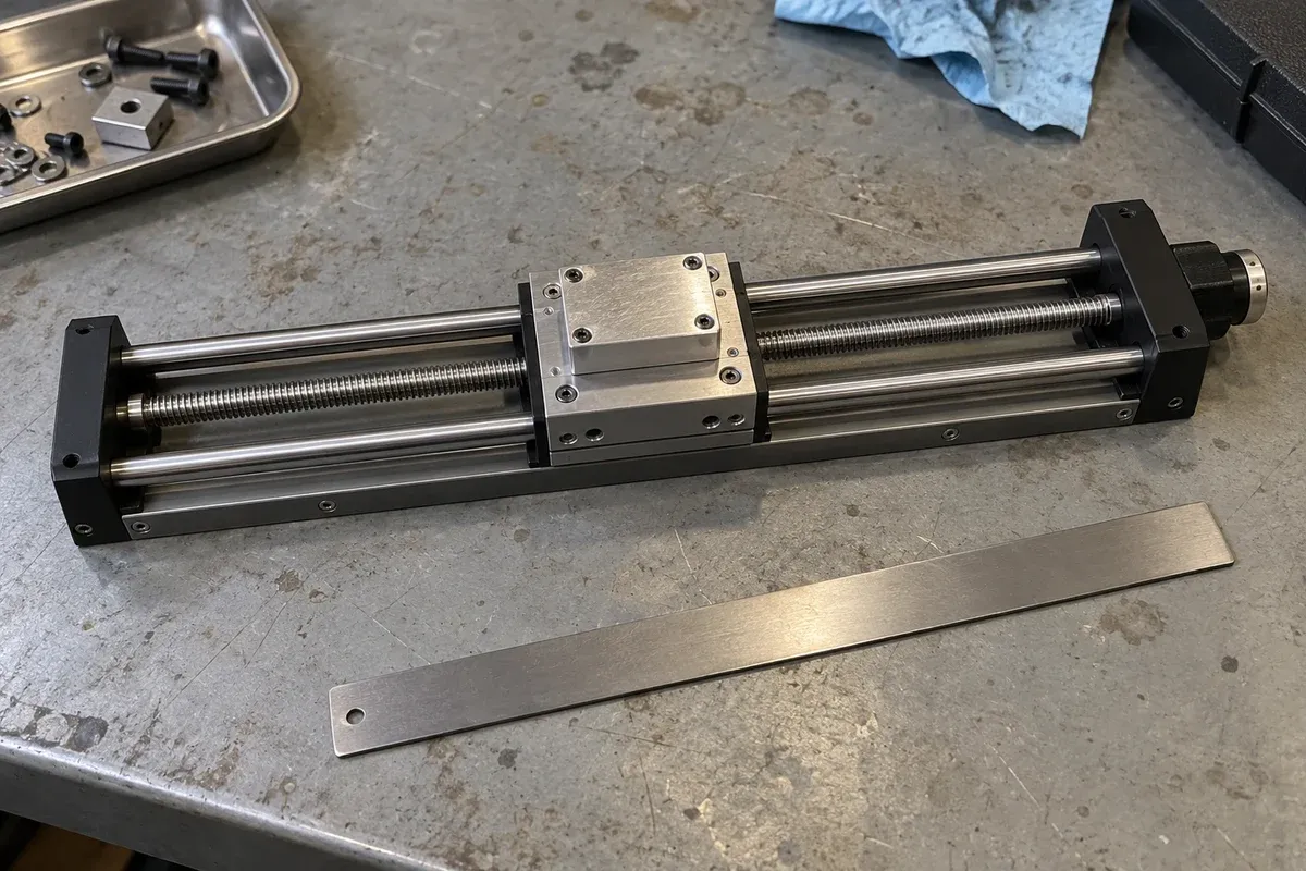
A software display can show more decimal places than a fixture can reliably use. When an application requests very small steps, first determine what those numbers mean: command units, nominal drive increments, measured carriage displacement or verified workpiece movement. These are different claims, and the distinction belongs in the software requirements as well as the mechanical specification.
A stepper motor produces incremental rotation; its driver supplies current to the windings. These are different roles from the motion controller that issues or coordinates commands. Dover Motion introduces the motor, while Oriental Motor shows why the motor/driver pairing matters. Identify the actual motor, driver, controller and transmission before assigning a step scale; none of the example motor details establishes the selected stage’s configuration.
Define the command scale explicitly
For planning, a screw-driven axis can be described by screw travel per revolution, motor steps per revolution and the selected subdivision of each step. Their combination produces a nominal conversion between command increments and distance. That arithmetic is useful for unit handling, but does not measure the resulting movement.
The Zaber manual uses device-specific conversion factors. Treat that as an example of documentation discipline. Obtain the actual conversion, units and configuration dependencies from the selected drive and controller provider; do not reuse another manufacturer’s numbers or syntax.
Record where conversion takes place. If a host library already accepts engineering units, a second conversion in application code can introduce a serious scaling error. Include rounding behavior, minimum accepted increment and any relevant representation limits in the interface review.
Separate three acceptance questions
The first question is whether software encodes the intended displacement correctly. This can be reviewed using documented conversions and non-moving software tests. The second is whether the drive accepts and reports the command as intended. The third is whether the physical point of interest moves sufficiently for the process.
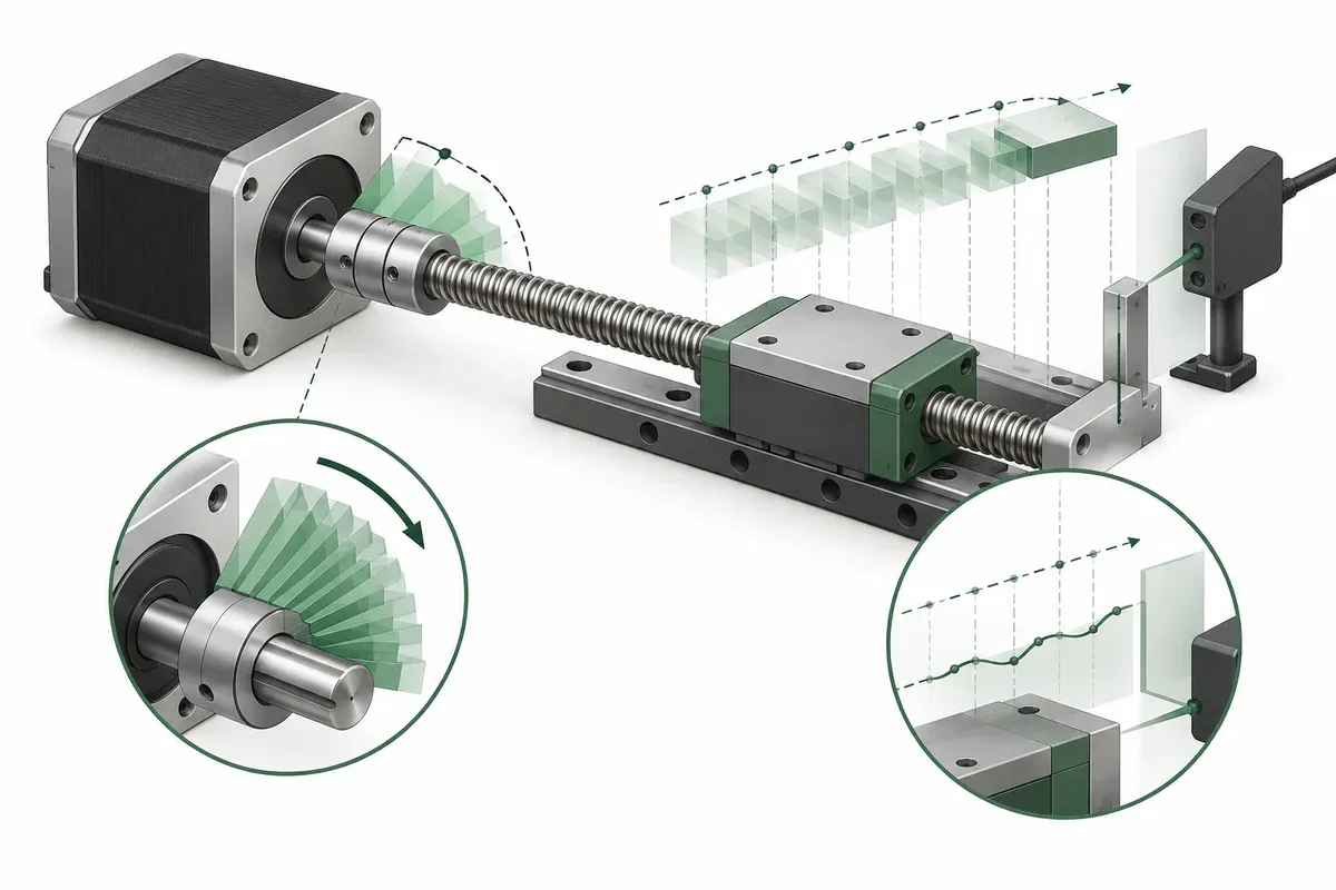
Microstepping changes the commanded subdivision of motor movement. It does not, by itself, certify that every subdivision becomes equal displacement at a loaded fixture. Friction, transmission behavior and the measurement arrangement belong in the physical evaluation. Avoid turning a calculated increment into a catalogue accuracy claim.
Use the specification guide when naming the results. Resolution, repeatability and positioning accuracy answer different questions. Reporting only the smallest command value hides the question the experiment must actually resolve.
Small-increment verification checklist
- Identify whether each recorded value is a command, controller report or independent measurement.
- Save the drive subdivision setting and approved distance-conversion basis.
- Define the process-relevant displacement and the point where it must be observed.
- Record payload, orientation, approach direction and measurement uncertainty.
- Include repeated increments and relevant reversals in the reviewed experiment.
- Retain unsuccessful or ambiguous observations rather than rounding them into success.
- State the conditions under which the resulting conclusion may be reused.
The checklist asks for a test design, not operating settings. A qualified reviewer should choose the instrument and procedure. The instrument needs enough capability to distinguish the proposed effect from its own uncertainty and noise.
Hypothetical nominal-increment calculation
Imagine a purely illustrative mechanism with 2 mm travel per screw revolution, 200 full motor steps per revolution and 10 commanded subdivisions per full step. With a direct one-to-one drive assumption, the nominal increment is 2 divided by 2,000 mm, or 1 micrometre. These invented values are not specifications for any listed stage.
The software team can verify that a 20 micrometre request becomes 20 nominal increments under that definition. The mechanical team still needs to establish what movement actually occurs at the workpiece. If repeated one-increment requests produce an irregular response, changing the displayed precision would not resolve the physical limitation.
For a different transmission ratio or configuration, the calculation changes. Keep every assumption next to the result so the arithmetic cannot be mistaken for a measured capability.
Release a bounded software assumption
Write the final assumption in terms of evidence: which increment was tested, under which conditions, and what the measurement supported. If the process needs reliable response to a particular step size, make that response an acceptance requirement rather than an inference from controller resolution.
Retest when a relevant drive setting, transmission component, payload or measurement geometry changes. Software may be able to request a smaller increment immediately, while the evidence for using it in production remains incomplete. Keeping these two states separate prevents an interface enhancement from silently becoming an unsupported accuracy promise.
Make the distinction visible in the operator interface too, so a displayed command increment cannot be mistaken for a fresh measurement of physical displacement.
Questions
Does more microstepping automatically improve accuracy?
No. It changes command subdivision; physical accuracy and useful incremental response require evidence.
Can calculated step size be used in unit conversion?
Yes, when the documented mechanism and drive configuration support the calculation. That remains separate from physical verification.
Where should small motion be measured?
At the point relevant to the process, or with a justified measurement relationship to it.
Sources & scope
Sources support the specific points described below. General engineering guidance and third-party examples do not establish a catalogue model's performance or suitability.
- Zaber ASCII Protocol Manual
Only device-specific conversion factors; the nominal screw calculation is hypothetical and the verification worksheet is original guidance.
Accessed - Dover Motion: Stepper Motors
Component-level introduction; not a specification for catalogue motors.
Accessed - Oriental Motor: speed–torque curves
Curve interpretation depends on the stated motor/driver combination.
Accessed
Related engineering resources
Continue reading
Motion Control & Automation
Absolute and relative moves in a repeatable work sequence
Choose absolute and relative move semantics, document units and references, and prevent duplicate execution during communication recovery.
Integration guide · 4 min read ·Motion Control & Automation
Acceleration and deceleration requirements for a loaded axis
Prepare load-specific acceleration and deceleration requirements without copying tuning values from an unloaded stage demonstration.
Integration guide · 4 min read ·From requirements to a quotation
Review your stage requirements
Share the motion envelope, payload, orientation and acceptance criteria. Request confirmation of the exact configuration before ordering.
Request a Quote