Key takeaways
- A visibly clean surface is not a verified mounting interface.
- Flatness, level and alignment describe different relationships.
- Use the selected stage’s installation requirements rather than borrowed tolerances.
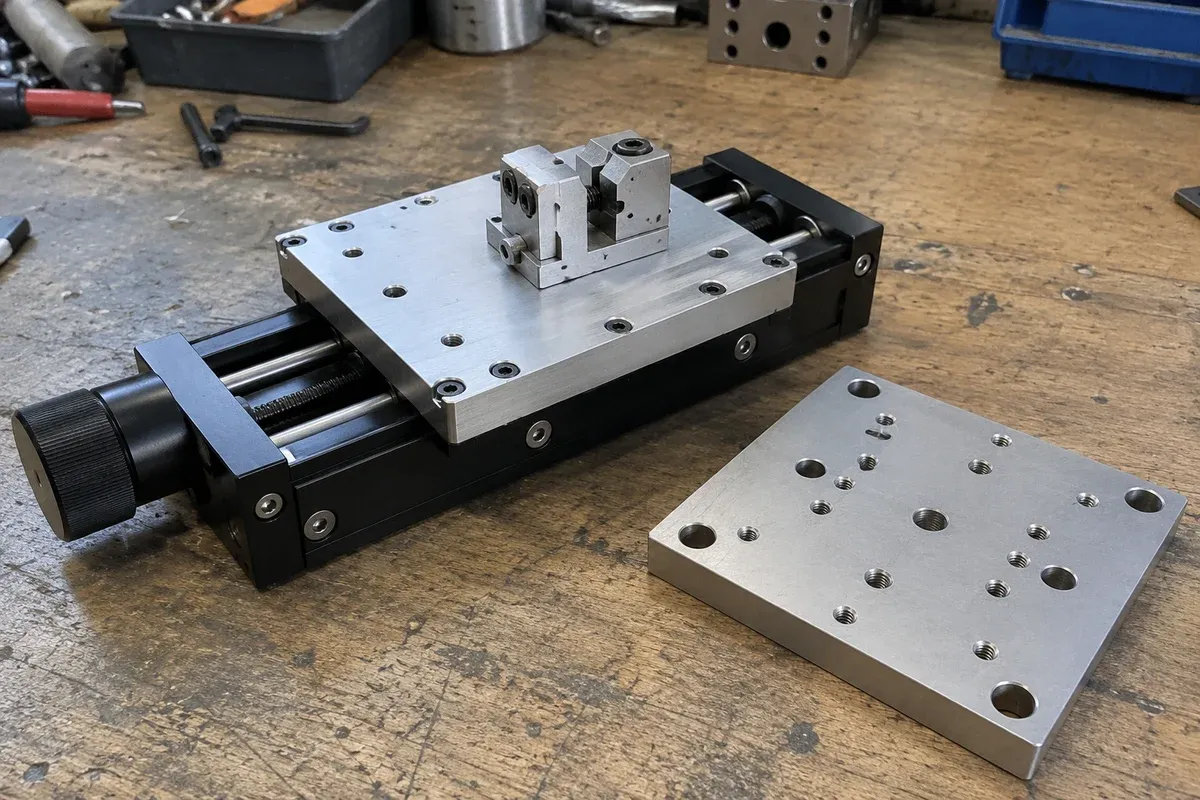
The support surface is part of the positioning assembly. Reviewing it before installation helps prevent a carefully chosen stage from being attached to an interface whose geometry or condition is unknown. The goal is a documented readiness decision, not an informal instruction to polish, shim or tighten the base until it appears satisfactory.
Obtain the installation requirements first
Identify the exact stage model, mounting orientation and intended support arrangement. Request the applicable requirements for the contact surface and attachment. A numerical limit from another stage manual may demonstrate that the issue matters, but it cannot establish the correct limit for your assembly.
For example, the Newport IDL165-LM installation manual includes model-specific mounting-surface requirements. None of its numerical requirements is adopted here. The useful lesson is to seek the corresponding approved information for the selected product before defining an inspection plan.
Distinguish the properties being reviewed
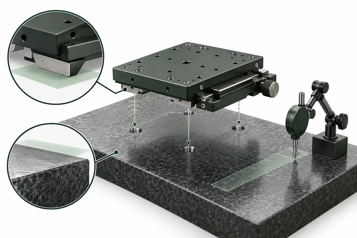
Flatness concerns the form of a surface. Level concerns its orientation relative to gravity. Parallelism and alignment concern relationships to other features. A support can satisfy one of these descriptions while failing another, so the readiness record should name the property rather than saying the base is good.
Also identify the actual contact footprint. A large plate may contain pockets, raised pads, coating transitions or nearby openings. Determine which regions are intended to contact the stage and which are deliberately relieved. The stage outline alone does not show whether the support matches the required bearing area.
Plan evidence appropriate to the requirement
Agree how the relevant surface properties will be inspected and recorded. Identify the measurement reference, equipment, sampled region and condition of the support. A drawing note without inspection evidence and an inspection result without a requirement are both incomplete.
Surface condition deserves its own observation record. Damage, burrs, contamination or coating defects near a contact region should be referred for disposition. Do not direct an installer to remove material or modify a precision interface without an approved method. Likewise, the presence of adjustment features should not be treated as permission to improvise an alignment procedure.
Consider the support in its installed state. If it is attached to another structure, the reviewer may need to assess that relationship rather than relying only on a loose-plate inspection. Document the condition under which the evidence was obtained so it can be compared with the final arrangement.
Support-readiness checklist
- Confirm the support drawing and stage installation-document revisions.
- Identify intended contact regions and attachment features.
- Separate form, orientation and alignment requirements.
- Record the inspection method and measurement reference.
- Document visible contact-surface defects and their disposition.
- State whether inspection represents the final supported condition.
- Leave unresolved tolerances or corrective actions open for review.
- Obtain readiness acceptance before the installation procedure proceeds.
This checklist is deliberately a review tool. It does not specify cleaning chemicals, abrasive processes, shimming practices or attachment torque. Those details depend on materials, surface treatment and approved instructions for the equipment.
Record how the support will be identified after inspection. A result attached only to a generic drawing can become disconnected from the actual plate used in the machine. Component identification, revision and inspection condition allow the installation team to confirm that the assessed interface is the one presented for assembly, especially when several similar bases exist. This is particularly important when a prototype base has been reworked between design reviews.
Hypothetical example: a reused inspection base
Suppose a laboratory plans to place a new stage on an existing baseplate. The base looks level and has the required attachment pattern. During the readiness review, the team discovers a raised region around a previously modified hole inside the proposed contact footprint.
Rather than assuming mounting pressure will resolve it, the team records the condition and requests a qualified disposition. It also checks whether the earlier inspection covered the support in its present installed state. This fictional example shows why visual level and matching holes are insufficient evidence of readiness.
Use the specification-method overview to keep component specifications separate from assembly evidence. For installation, the decisive information remains the selected stage’s approved interface requirements and a traceable assessment of the actual support.
Questions
Must every stage have the same surface flatness?
No. Obtain the requirements for the exact stage and mounting arrangement; another product manual is not a substitute.
Is a level base necessarily flat?
No. Level describes orientation relative to gravity, while flatness describes the surface form.
Should a technician correct an uneven base by tightening harder?
Do not improvise a correction. Refer the condition to the qualified mechanical reviewer and use the approved installation method.
Sources & scope
Sources support the specific points described below. General engineering guidance and third-party examples do not establish a catalogue model's performance or suitability.
- Newport IDL165-LM installation manual
Illustrates that support-surface requirements are model-specific installation specifications; its numerical requirements do not apply to this catalogue.
Accessed
Related engineering resources
Continue reading
Accuracy & Metrology
Accuracy, repeatability and resolution: three separate acceptance questions
Turn accuracy, repeatability and resolution into separate acceptance requirements, with a worksheet for evidence, conditions and decisions.
Verification guide · 4 min read ·
Applications & System Design
Defining degrees of freedom for a fiber-array-to-chip alignment bench
Map translations, rotations and pivot locations for a proposed fiber-array alignment bench without assuming six axes solve the optical task.
Application guide · 4 min read ·From requirements to a quotation
Review your stage requirements
Share the motion envelope, payload, orientation and acceptance criteria. Request confirmation of the exact configuration before ordering.
Request a Quote