Key takeaways
- Define coordinate directions before choosing axis count.
- Specify the optical pivot and the consequences of rotating away from it.
- Separate assembly adjustment from motion required during each alignment.
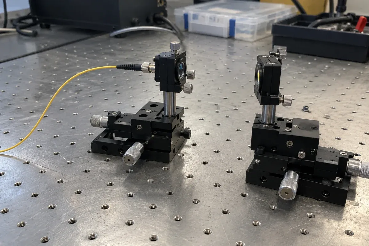
A fiber-array-to-chip bench should start with a coordinate sketch, not a shopping list of axes. “XYZ plus rotation” is incomplete until the directions, reference frame and point of rotation are stated. The same axis name can mean different physical motions to the optical designer, fixture builder and controller programmer.
The following is a conceptual requirements exercise. It makes no claim that the catalogue provides a complete fiber-alignment solution, or that any particular combination reaches an optical coupling target.
Establish the optical coordinate frame
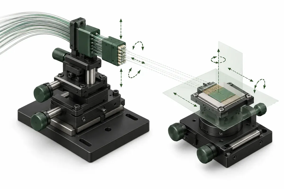
Choose a reference fixed to the chip fixture and mark the nominal optical propagation direction. Draw the two transverse directions and label all three rotations using that drawing. Include an explicit positive direction for each motion. Put this sketch in the requirements package so that a later software axis name can be traced to a physical movement.
Next identify the point whose position matters. It could be a reference on the fiber-array face, a selected channel or another feature defined by the optical design. A coordinate at the stage mounting surface is not automatically a coordinate at that interface. Record the holder offset and the method used to locate it.
Separate adjustment from active correction
Create one row for each translational and angular degree of freedom. For each row, ask whether it is established during assembly, changed between parts, or adjusted while evaluating the optical signal. This produces a defensible division between fixed tooling, manual setup and commanded motion.
Do not remove an axis merely because one prototype aligned without using it. That prototype may not represent holder tolerances, package variants or repeated loading. Conversely, do not motorize every possible correction without a reason. Additional axes introduce interfaces and control responsibilities that must be justified by the experiment.
Locate the pivot before comparing mechanisms
PI’s array assembly discussion identifies coupled translation and rotation during array alignment. That is a reason to describe the pivot explicitly; it is not evidence that another stage stack reproduces PI’s alignment capability.
For a proposed angular axis, draw the intended rotation center and the actual mechanical center. Ask how the optical interface moves when those points differ. A geometrical model can help screen the design, but its offsets must come from the assembled fixture rather than nominal stage dimensions alone.
Also inspect what sweeps through space during the rotation. A cable clamp or fiber bend may determine usable travel before the stage reaches its catalogue angular limit. Request confirmation of the complete angular envelope with the intended adapters and holders.
Practical degree-of-freedom worksheet
- Record the fixed reference, optical interface and positive coordinate directions.
- For each direction, state the disturbance or variation it must correct.
- Classify its use as assembly adjustment, changeover or active alignment.
- Record the desired pivot and all holder offsets used to realize it.
- Mark the cable, tool and neighboring-part envelopes at the angular extremes.
- Identify the measurement that proves each adjustment helped the optical objective.
- List any correction that depends on coordinated motion across multiple axes.
Keep “required but not yet quantified” as an allowed worksheet entry. Resolving it through an experiment is preferable to specifying a correction range copied from an unrelated product page.
Hypothetical example: an unnecessary-looking angular axis
Imagine an evaluation fixture that aligns one central channel successfully using transverse translation. The team considers eliminating angular adjustment. Its next test uses an array with channels spread across a wider face, and the requirements review asks whether all channels can meet their individual criteria together.
The correct response is not to assume that another motor will solve the problem. The team retains the angular direction as an unresolved requirement, maps the relevant pivot and defines a trial that observes the individual channels while making controlled, authorized adjustments. This is a proposed investigation, not a reported optical result.
Release a geometric brief, not a promise
The final deliverable should show which directions must be available and why. Include the holder drawing, axis allocation, remaining uncertainties and proposed verification method. Compare multi-axis assemblies and goniometer geometry as possible mechanical building blocks only. Their suitability depends on exact configuration data and system-level testing, including the optical measurement and control method.
Questions
Does a fiber array always require six motorized axes?
No universal count follows from the application name. Geometry, fixture constraints and the alignment process determine which adjustments must remain available.
Is a goniometer automatically centered on the optical interface?
No. Its specified rotation-center geometry must be reconciled with the holder and optical interface.
Can a fixed adjustment replace a motorized axis?
It can be evaluated when that direction remains adequately constrained across loading and part variation; test the assumption before removing the axis.
Sources & scope
Sources support the specific points described below. General engineering guidance and third-party examples do not establish a catalogue model's performance or suitability.
- PI: Case Study, Photonic Array Device Assembly
Third-party example of optical feedback, coupled alignment axes and attachment; no performance transfer to this catalogue.
Accessed
Related engineering resources
Continue reading
Mounting & Mechanical Integration
Checking the support surface before installing a precision stage
Organize a support-surface readiness review around documented requirements, contact geometry, surface condition and traceable inspection evidence.
Integration guide · 4 min read ·
Accuracy & Metrology
Accuracy, repeatability and resolution: three separate acceptance questions
Turn accuracy, repeatability and resolution into separate acceptance requirements, with a worksheet for evidence, conditions and decisions.
Verification guide · 4 min read ·From requirements to a quotation
Review your stage requirements
Share the motion envelope, payload, orientation and acceptance criteria. Request confirmation of the exact configuration before ordering.
Request a Quote