Key takeaways
- List everything carried by each axis in every candidate layout.
- Stack order affects access and the functional point, not just footprint.
- Treat axis-layout comparisons as concepts requiring configuration review.
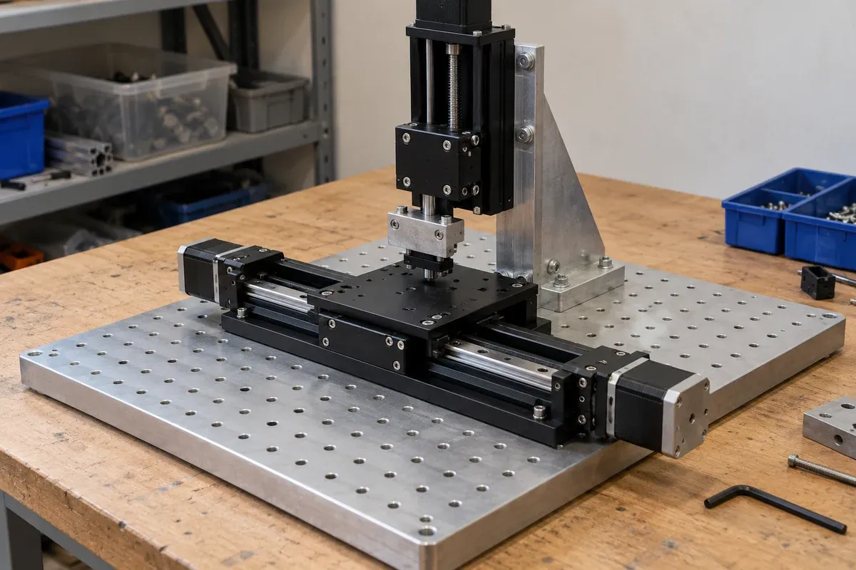
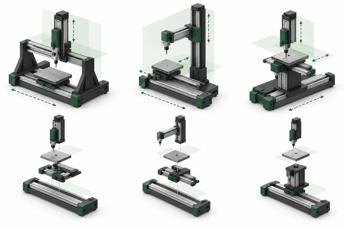
An XYZ label describes three directions of motion, but it does not determine the physical arrangement that produces them. A vertical axis above two horizontal axes creates a different machine from a horizontal pair carried by a lift. Compare layouts while changes are inexpensive, using the actual workpiece and tooling rather than three empty stage blocks.
Draw the moving assembly for each candidate
For every axis, shade the components that move when that axis moves. Include motors on upper stages, brackets, nests, adapters and service attachments. This simple drawing reveals why the payload seen by a lower axis can be much larger than the part being positioned.
Prepare a mass inventory tied to the configuration. Keep uncertain masses explicit, particularly for prototype tooling that has not been designed. Identify the approximate center of mass of each carried group and how its location changes with other axis positions. These are inputs for engineering review, not permission to infer allowable loading from a single catalogue number.
Compare support and functional-point geometry
Place the point that matters to the process on each sketch. It might be a probe tip, camera field center or gripper contact. Measure its nominal location relative to the support structure and note the positions where offsets become largest.
A multi-axis design reference explains that angular errors combined with offsets affect the point of interest. The practical implication here is to include functional-point geometry in layout review. It is not a formula for predicting this catalogue’s assembled accuracy from incomplete component data.
A low stack may improve access in one direction while blocking another. A separate vertical structure may reduce carried hardware but require more surrounding space. Compare these tradeoffs as alternatives rather than declaring one universal XYZ order best.
Include service access and work flow
Show how a part enters and leaves the fixture. Then show the access needed for the normal tooling change and for qualified maintenance. A compact arrangement may become impractical if the upper stages cover mounting screws or if the operator must reach through a moving structure to change a nest.
Services deserve an early sketch. Identify the fixed entry point, the components that move together and the transitions between stages. Different stack orders can change the number of moving transitions. Do not leave cable routing to a final packaging exercise after the structural layout is frozen.
Candidate-layout checklist
- Sketch the same workpiece and functional point in each arrangement.
- List the carried mass group for every axis.
- Identify the positions producing the largest payload offsets.
- Compare total height, occupied footprint and surrounding access.
- Trace cable and hose transitions through the proposed stack.
- Check part-loading and tooling-removal paths.
- Record the configuration questions requiring supplier review.
- State what assembled-system evidence the application needs.
Use a short decision record that says why a candidate was retained or rejected. Avoid scoring unknown load capacity as a positive simply because a concept looks compact. An unresolved critical interface should remain visibly unresolved in the comparison.
Include the supporting structure in the comparison. Two layouts with identical stages can require very different bases or uprights. If the support is outside the current design scope, name its required interfaces and the person responsible for resolving them. Otherwise the apparently preferred stack may depend on a support that has never been assessed.
Hypothetical example: moving the sample or the camera
Suppose an inspection station needs XY positioning and a focus adjustment. Concept A places a Z axis and camera above an XY sample fixture. Concept B carries the complete XY fixture on a vertical lift. The second concept may simplify camera mounting, but it asks the lift to move the horizontal assembly as well as the sample.
The team compares working-height range, mass groups, service routing and the measurement reference for both concepts. It then requests configuration-specific loading and interface information before selecting either. No payload capacity or achievable focus performance is implied by this hypothetical comparison.
Review multi-axis stages and vertical lifts as different starting architectures. The useful enquiry includes the full proposed layout and its operating positions, so the response can address the assembled arrangement instead of isolated axis names.
Questions
Should the longest-travel axis always be on the bottom?
It is a useful layout consideration, but loading, support and application geometry can justify another arrangement. Review the complete system.
Does the bottom axis carry only the workpiece?
In a serial stack it also carries the upper stages, adapters, holders and attached services that move with it.
Can changing stack order preserve the same accuracy?
Do not assume so. The geometry and error relationships change and need assessment at the functional point.
Sources & scope
Sources support the specific points described below. General engineering guidance and third-party examples do not establish a catalogue model's performance or suitability.
- Zaber multi-axis accuracy guide
Supports the narrow general principles that reference frames, assembly alignment and tool-point offsets matter; no system performance is inferred.
Accessed
Related engineering resources
Continue reading
Mounting & Mechanical Integration
Evaluating support, damping and vibration isolation for stage fixtures
Define stage-fixture vibration problems through support, damping, isolation, disturbance paths and configuration-specific measurement evidence.
Integration guide · 7 min read ·Mounting & Mechanical Integration
Keeping optical working height consistent across a multi-axis fixture
Create a working-height budget that connects the optical reference to bases, adapters, stages and holders across the complete fixture.
Integration guide · 4 min read ·From requirements to a quotation
Review your stage requirements
Share the motion envelope, payload, orientation and acceptance criteria. Request confirmation of the exact configuration before ordering.
Request a Quote