Key takeaways
- Map each required adjustment to a named translation or rotation.
- Separate setup adjustments from movements needed during operation.
- Specify the rotation axis explicitly instead of relying on the symbol theta.
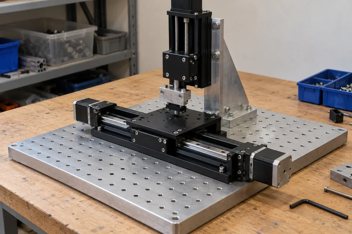
Describe the task without naming an axis package
Begin with what the workpiece must do relative to the tool, sensor or reference. It may need to move across a plane, change height, rotate its orientation, or combine several of these actions. Write those requirements in ordinary language before choosing a catalogue label.
Newport’s motion terminology describes three translational and three rotational degrees of freedom in space. Most fixtures do not need independent control of all six. The selection task is to identify which motions remain necessary after the fixture and stationary structure have constrained the workpiece.
Separate operating motion from setup adjustment
List each adjustment and mark when it occurs. Some movements happen every cycle; others are needed only when a fixture is installed or a product variant changes. This distinction can affect the architecture, but it should be a deliberate design decision rather than an assumption that every adjustment needs a motor.
In a hypothetical camera-inspection task, a flat sample must visit several positions across its surface while the working distance remains fixed. That suggests reviewing two in-plane translations. If samples arrive with different heights, the design also needs a way to establish working distance. Whether that requires an automated Z axis depends on the process, changeover and fixture strategy.
The example identifies questions, not a validated system. Keep any proposed fixed or manual adjustment in the review so it is not forgotten when the motion package is ordered.
Define coordinates on the actual machine
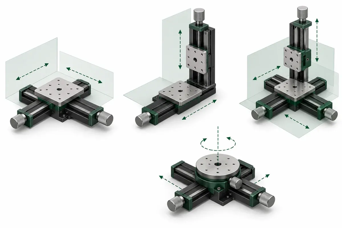
Draw arrows for X, Y and Z and identify their reference frame. Label the positive directions. For a rotation, draw its axis rather than writing only theta. A symbol used in a product title does not tell another engineer how your fixture is oriented in the machine.
The multi-axis family includes XY, XZ, XYZ and XYθ configurations. XY describes two translations in a plane; XZ combines a horizontal and a vertical translation in the usual machine description; XYZ adds a third translation. The exact physical arrangement and per-axis ranges must still be read from the selected configuration.
If the mechanism is installed in an unusual orientation, state that explicitly. Do not rely on an axis letter to communicate gravity loading. Coordinate naming and permissible mounting orientation are separate matters.
Convert task positions into per-axis requirements
Write the coordinates of the required positions and calculate the span independently for each axis. Include approach, loading and recovery positions. Do not use a single diagonal distance as the travel requirement for both axes.
As a hypothetical example, two locations differ by 12 mm in X and 9 mm in Y. The straight-line separation is 15 mm, but the coordinate changes are still 12 mm and 9 mm. Additional positions can increase either span. This elementary geometry does not establish trajectory capability; it only prevents a path length from being confused with an individual axis requirement.
For angular motion, list the orientations and transition paths separately. A planar positioning task with an orientation adjustment needs a different review from a task that tilts the workpiece about an elevated point. The latter may call for a different angular architecture even though both are casually described as adding rotation.
Check what each additional axis carries and changes
Adding an axis also adds an interface, space claim and integration responsibility. Identify which mechanism carries which other components. Check the combined moving envelope rather than reviewing each axis in isolation.
A degree-of-freedom review checklist can include:
- The physical task associated with every axis.
- Whether the motion is required during operation or setup.
- The coordinate arrows and rotation-axis location.
- Required span and sequence for each axis.
- Carried components and installation orientation.
- The measurement or observation that will confirm success.
If an axis has no clear task, ask why it is present. If a task has no corresponding motion or fixture provision, the architecture is incomplete.
Select the minimum complete arrangement
Use the axis map to shortlist configurations, then request exact travel, mounting and load information. Minimum complete means every required motion is addressed; it does not mean removing an axis merely to simplify the list. Preserve the map with the application drawing so later process changes can be evaluated against it. This makes the final choice explainable in terms of the work, rather than a preference for the package with the largest number of axes.
Questions
What does XYθ add to XY?
It adds an angular degree of freedom to planar translation, but the actual rotation axis and mechanical arrangement must be confirmed from the configuration drawing.
Do equal X and Y travel values cover a diagonal move?
Check the required coordinate displacement on each axis. A diagonal path is not an extra axis, and its length alone does not specify the individual X and Y requirements.
Should every setup adjustment be motorized?
Not necessarily. Decide which adjustments need automatic movement during the process and which can be established during setup. Review any manual adjustment or fixed fixture against the task.
Sources & scope
Sources support the specific points described below. General engineering guidance and third-party examples do not establish a catalogue model's performance or suitability.
- Newport motion terminology
Defines three linear and three rotational degrees of freedom and a motion coordinate-system convention. The task mapping and numerical example are original.
Accessed - Multi-axis stages
Lists XY, XZ, XYZ and XYθ assemblies with configuration-specific axis descriptions.
Accessed
Related engineering resources
Continue reading
Stage Selection & Buying Guides
Comparing screw, linear-motor, piezo, flexure and air-bearing stages
Compare stage actuation, guidance, feedback and support separately, then request configuration-specific evidence for the intended movement and load.
Selection guide · 8 min read ·
Stage Selection & Buying Guides
Integrated XY assembly or separately stacked single axes?
Compare an integrated XY assembly with stacked single axes by assigning alignment, loading, mounting and assembled-system verification responsibilities.
Selection guide · 8 min read ·From requirements to a quotation
Review your stage requirements
Share the motion envelope, payload, orientation and acceptance criteria. Request confirmation of the exact configuration before ordering.
Request a Quote