Key takeaways
- Actuation and guidance describe different functions; one stage can combine several architecture labels.
- Piezo motors, piezo strain actuators and flexure guidance must not be treated as one mechanism.
- An air bearing is a support/guidance choice, not a drive or a performance guarantee.
- Compare exact configurations at the workpiece point; no architecture establishes a universal rating or catalogue substitute.
- Cartesian axis labels do not establish stack/gantry topology or a complete robot package.
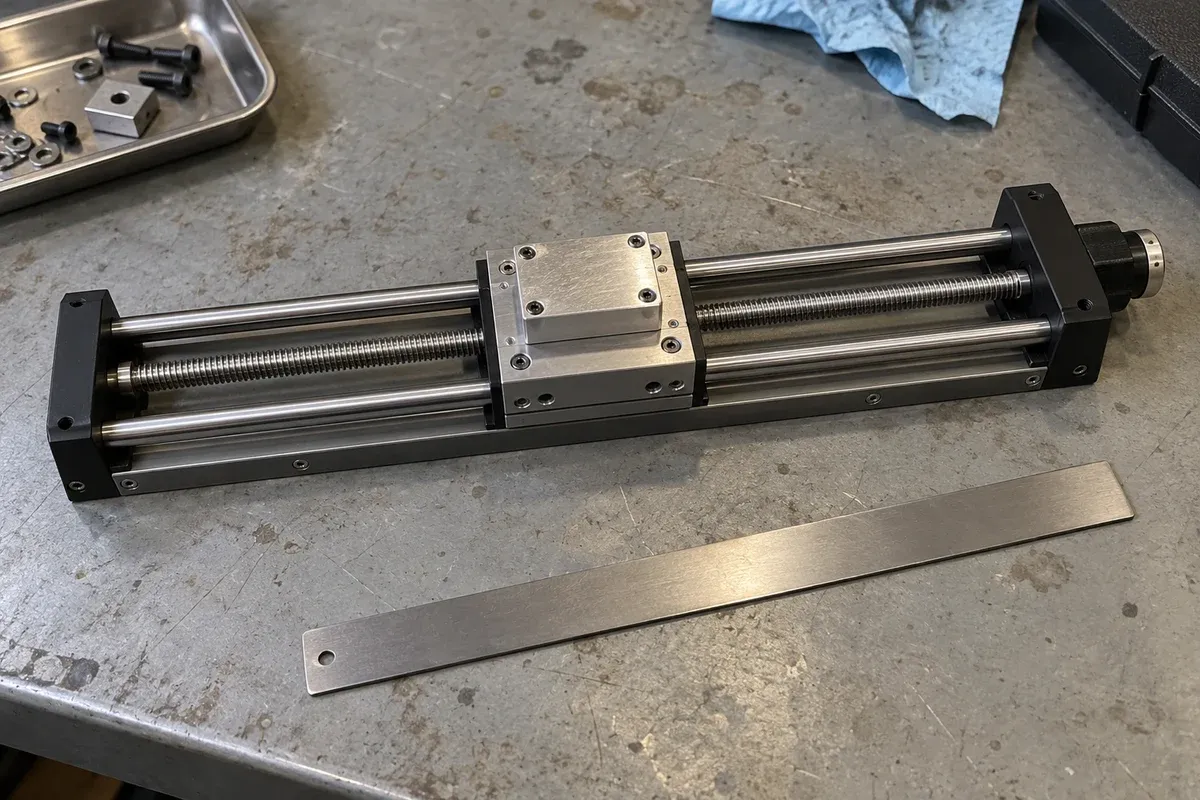
A useful stage comparison begins with the required motion and the complete supplied system. “Screw,” “linear motor,” “piezo,” “flexure” and “air bearing” are not five mutually exclusive product classes. Some describe how force is produced; others describe how the platform is supported and constrained. A stage can combine several of them.
This guide supports an architecture shortlist. Third-party examples explain mechanisms, not the availability, compatibility or performance of PositioningStages catalogue models. It provides no universal travel, accuracy, speed or payload ranking.
Separate actuation, guidance, feedback and support
Actuation produces the force or torque that moves the load. Guidance constrains unwanted motion while allowing the intended movement. A linear bearing or guide supports and guides relative translation; rolling-element designs use balls or rollers between moving and stationary members. Their job differs from that of a motor or screw, even when both arrive inside one housing.
Feedback measures a physical quantity at a particular location. The controller may use it to correct motion, monitor a condition or display a position. The supporting structure carries the assembly and establishes its mounting reference. Describe all four functions before comparing performance.
Aerotech’s linear-motor application guide shows direct-drive stages using different bearing styles. Its architecture examples support asking separate questions about motor and guidance. The guide is historical technical material, not a current quotation or a rating for another supplier’s stage.
Examine the complete screw-driven axis
A screw converts rotation into nominal linear advance. A ball screw uses rolling balls between shaft and nut, as described in THK’s mechanism overview. A sliding screw uses a different contact arrangement. Identify which mechanism is proposed rather than treating every screw drive as identical.
The screw does not, by itself, define platform guidance, feedback location or installed load capacity. Ask about reversal behavior, support bearings, coupling, lubrication and the operating sequence. Lead-based command arithmetic cannot establish reliable minimum motion at the workpiece.
A screw-driven candidate may fit a fixture whose verified movement and installation requirements are met without changing architecture. Retain it on that evidence. Do not assume zero lost motion, maintenance-free operation or unpowered vertical holding from the drive name. Confirm those requirements for the actual supplied configuration.
Understand what a direct linear motor changes
An electromagnetic linear motor produces force along a translation axis without a rotary screw conversion. It still needs guidance and a drive/control arrangement. Identify the position-observation or feedback scheme separately. PI’s linear-motor stage overview illustrates combinations of electromagnetic motor, encoder and bearing technologies.
Removing a screw transmission changes the design questions; it does not remove them. Request evidence for force over the intended movement cycle, thermal conditions, cable forces and position observation. Ask how the supported load behaves during interruption, especially in an orientation affected by gravity.
For a scanning task, compare measured velocity behavior, path error and process timing under the actual payload. For point positioning, compare settling and repeated arrival at the functional point. A motor’s peak force or a stage’s maximum speed does not establish either application result.
Distinguish piezo strain stages from piezo motor stages
Piezoelectric material changes shape under an applied electric field. A piezo strain actuator can use that deformation directly or through an amplification mechanism. In a flexure-guided piezo stage, elastic members guide the resulting platform movement. Assess the specified working range, load, drive electronics and position measurement together.
Piezo motors use a different operating arrangement. Inertia or stick-slip drives, walking drives and ultrasonic resonant drives can generate repeated motion through their particular contact sequences. PI’s piezo-motor overview distinguishes these mechanisms from flexure-guided strain positioners. Its product claims are not transferred here.
Consequently, “piezoelectric stage” does not always mean “flexure stage,” and a piezo motor is not a complete stage merely because it produces motion. Ask which principle is used, how the moving part is guided and what occurs while moving, dwelling and reversing. For strain-actuated systems, request the relevant hysteresis, creep and closed-loop evidence rather than assuming the smallest electrical command is an achieved displacement.
Treat flexures and air bearings as guidance choices
A flexure guide permits movement through elastic deformation of designed members instead of rolling or sliding contact at the guiding joint. Its geometry constrains the allowed displacement and other motion components. An XY flexure stage therefore needs evidence for useful travel in both directions, coupled or parasitic motion, loading and the actuator arrangement. “Flexure” alone supplies none of those numerical limits.
PI’s piezo-stage collection provides examples of flexure-guided positioners. Identify their guidance and actuation separately, and avoid assigning one configuration’s range or behavior to the entire label.
An air bearing supports relative movement on a gas film; it is not a drive. PI’s air-bearing collection includes linear and rotary positioning arrangements. A precision air-bearing table still requires an identified actuator, reference and controller where motorized motion is required.
Request the selected system’s air quality, supply, monitoring, mounting and interruption requirements. The Aerotech ABRS manual demonstrates that these are configuration-specific obligations. Its pressure and installation instructions are not generic design values. Do not confuse a precision positioning table with an air-supported device for moving heavy equipment across a floor.
Keep direct-drive rotary terminology explicit
In direct-drive rotary motion, the load is coupled directly to the motor rotor rather than through an intermediate gear or belt transmission. A bare torque motor is not automatically a supported rotary stage. The stage also needs bearings, payload interfaces, position evidence and controls appropriate to its task.
Aerotech’s direct-drive rotary example is one implementation, not a proposed substitute for a catalogue model. Compare torque and inertia over the required cycle, angular error motion and holding behavior separately. Direct drive does not establish a hollow aperture, unlimited cable rotation or an air bearing.
Distinguish Cartesian coordinates from stack or gantry structure
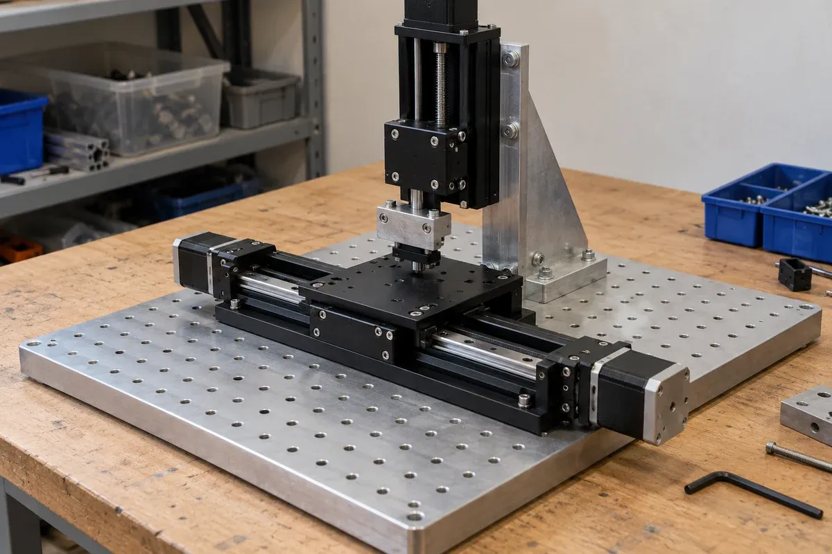
Cartesian terminology describes coordinates and linear-axis directions; it does not choose the physical support topology. In a serial stack, a lower axis carries upper mechanisms as well as their fixture and workpiece. A gantry uses a spanning member and support arrangement that can provide a different load path. Zaber’s multi-axis guide distinguishes stacked/cantilever systems from gantries; its examples do not establish a universal performance advantage. Draw which masses move with each axis, trace forces into the base, and identify offsets, joining interfaces and alignment references for both layouts.
For a gantry proposal, identify which supports are guided, driven or passive. Where multiple drives move coupled members, request the documented synchronization, reference-establishment and fault-handling strategy; not every gantry is dual-drive. Assign interface design, assembly alignment, controls integration and assembled verification to named parties. A Cartesian or gantry robot may denote a complete automation package. Coordinates and stages alone do not include its end effector, software or machine-level qualification. This comparison addresses stage-buyer architecture and responsibilities, not an offer of a complete industrial robot or controller package.
Compare candidates on one application worksheet
Use one fixture drawing and movement sequence for every candidate. This original worksheet organizes evidence rather than awarding architecture scores.
| Decision | Evidence to request for each configuration |
|---|---|
| Mechanism identity | Actuator principle, transmission, guidance, feedback location and support arrangement. |
| Working motion | Required positions or path, reversals, observation interval, settling condition and handling travel. |
| Load and geometry | Complete carried assembly, orientation, force directions, moments and functional-point location. |
| Positioning result | Separate accuracy, repeatability and minimum-motion evidence with test conditions. |
| Integration obligations | Controller, drive, cables, utilities, thermal management and interruption behavior. |
| Delivery boundary | Included components, customer-owned interfaces and assembled acceptance responsibilities. |
For a hypothetical optical bench, a coarse positioning task and a local fine adjustment may lead to a combined architecture rather than one universal winner. Combining mechanisms also adds interfaces, coordinate relationships and verification work. No performance follows merely from stacking a fine-adjustment device on a longer-travel axis.
Retain a conditional shortlist
Record why a candidate fits, which evidence remains missing and who must supply it. Compare alternatives at the same workpiece point and under the intended configuration. A smaller command increment, different bearing label or absent screw cannot replace that comparison.
The site’s linear-stage family identifies its documented screw-driven candidates. Use the stage selector and specification basis guide within their stated scope. This broader architecture guide does not add linear-motor, piezo, flexure, air-bearing or direct-drive rotary products to that catalogue, and it does not establish a replacement for any named supplier model.
Questions
Is an air-bearing stage driven by the air bearing?
The air bearing supports relative movement on a gas film. Identify the actuator and control arrangement separately; the bearing label does not establish motorized motion.
Are all piezoelectric stages flexure-guided?
No. Piezo strain positioners and piezo motor stages use different principles, and their guidance arrangements vary. Identify the actuator and guide used in the exact configuration.
Does a linear stage necessarily contain a linear motor?
No. Linear describes the intended translation. A screw-driven stage, an electromagnetic linear-motor stage or another actuator arrangement can provide it.
What should be checked on an XY flexure stage?
Confirm useful motion in both directions, cross-axis or parasitic movement, payload geometry, actuator arrangement and position evidence at the required point. The flexure label supplies no universal range or accuracy.
Does direct-drive rotary motion eliminate every positioning error?
No. Directly coupling the load to the rotor does not remove bearing error motion, feedback limits, controller behavior or fixture effects. A bare motor is also different from a supported stage.
Sources & scope
Sources support the specific points described below. General engineering guidance and third-party examples do not establish a catalogue model's performance or suitability.
- THK: Ball Screw
Supports only rolling balls between the screw shaft and nut and the rotation-to-translation mechanism; no THK rating transfers to a catalogue stage.
Accessed - Aerotech: Linear Motors Application Guide
Historical technical reference distinguishes linear-motor drive from air, crossed-roller and linear-guide bearing choices; no current specification or numerical rating is adopted.
Accessed - PI: Direct-Drive Linear Motor Stages
Illustrates electromagnetic linear motors combined with feedback and different bearing architectures; not evidence of our product availability or performance.
Accessed - PI: Piezo Motors and Positioners
Distinguishes inertia, walking and ultrasonic piezo motors from flexure-guided strain-positioning arrangements; vendor performance and compatibility claims are not transferred.
Accessed - PI: Piezo Flexure Nanopositioners
Provides examples of flexure-guided positioners; supports identifying actuation and guidance separately without adopting numerical ranges or claiming nonflexure variants from this collection.
Accessed - PI: Air Bearings and Stages
Identifies linear and rotary positioning architectures with air bearings; no model suitability, accuracy or load result is transferred.
Accessed - Aerotech: ABRS Hardware Manual
Section 1.4 illustrates configuration-specific air-supply and interruption requirements; pressure values, installation instructions and qualifications are not generalized.
Accessed - Aerotech: ACS-LP Direct-Drive Rotary Collet Stage
Illustrates a complete direct-drive rotary implementation distinct from a bare motor; no numerical or replacement claim is made.
Accessed - Zaber: Multi-Axis Accuracy Guide
Distinguishes Cartesian stacked/cantilever and gantry topologies, including dual-drive and passive secondary-axis examples. Supports load-path and conditional synchronization questions only; no universal performance ranking, robot package or catalogue capability is inferred.
Accessed
Related engineering resources
Continue reading
Stage Selection & Buying Guides
Choosing a vertical lift instead of mounting a linear stage vertically
Compare a dedicated vertical lift with a vertically mounted linear stage by checking layout, gravity loading, support and configuration-specific evidence.
Selection guide · 4 min read ·Stage Selection & Buying Guides
Choosing XY, XZ, XYZ or XYθ from the required degrees of freedom
Translate the task into independent motion directions, then choose XY, XZ, XYZ or XYθ with explicit axis definitions and per-axis travel requirements.
Selection guide · 4 min read ·From requirements to a quotation
Review your stage requirements
Share the motion envelope, payload, orientation and acceptance criteria. Request confirmation of the exact configuration before ordering.
Request a Quote