Key takeaways
- Compare the delivered assembly boundary, not just the axis count.
- Include upper-axis mass and fixture geometry in the lower-axis review.
- Request assembled evidence instead of reusing isolated-axis specifications.
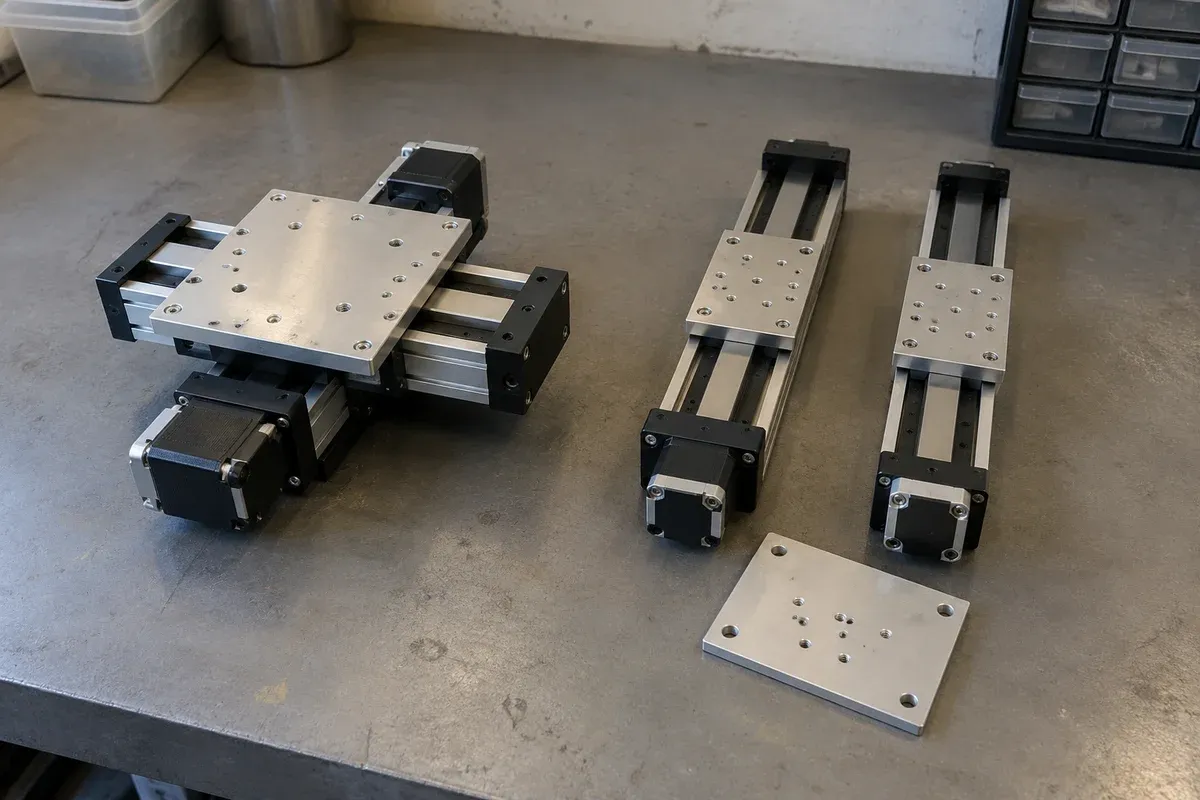
Compare what arrives, not just what moves
Direct answer
Choose the integrated route when the offer explicitly assigns the joining-interface design, assembly and agreed assembly-level evidence to the supplier. Consider separate axes when reuse or configuration flexibility serves the project and a named team can own those tasks. Either route still needs a review of the installed load, geometry, controls and application acceptance; the architecture label alone does not settle the choice.
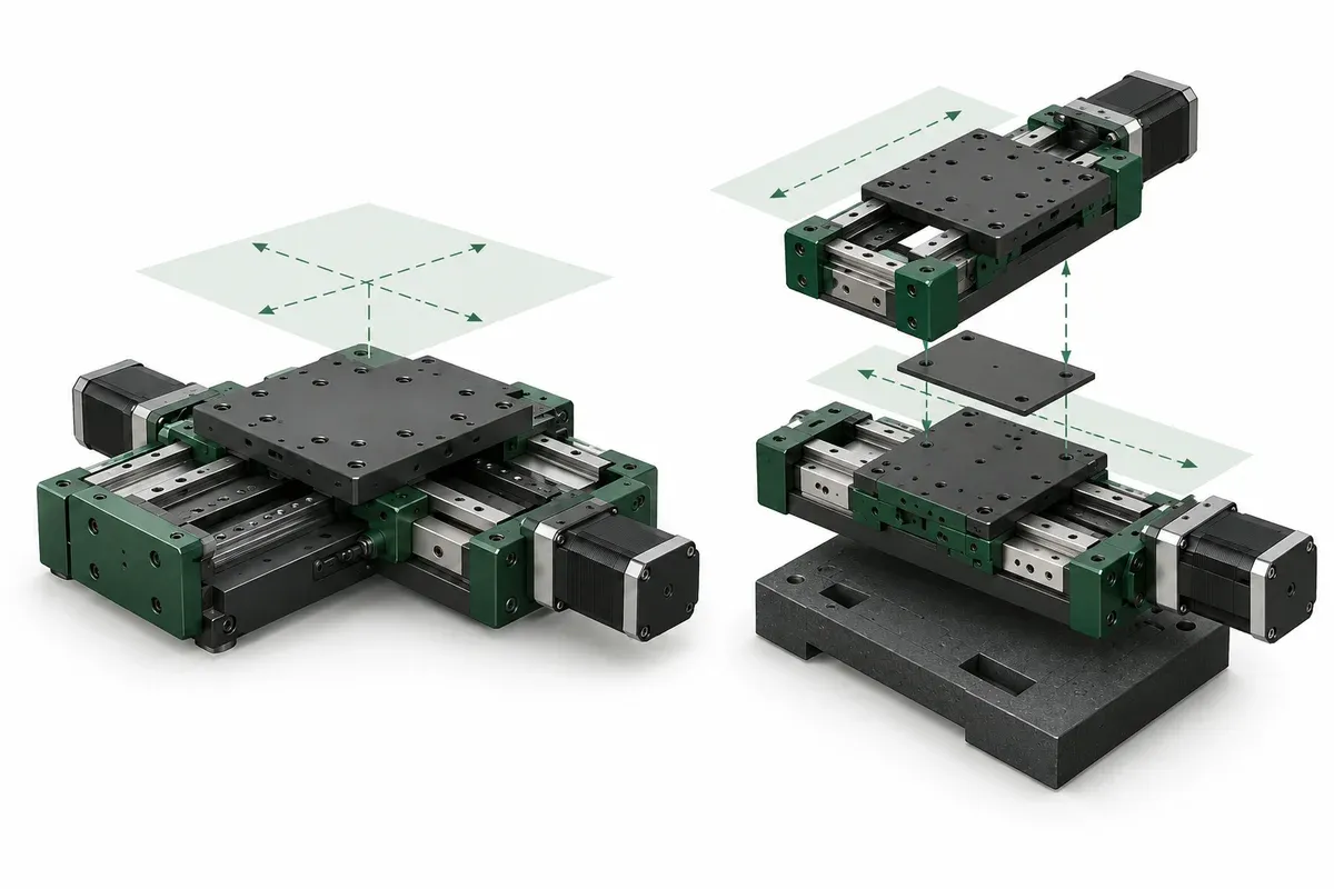
An integrated XY assembly and two separately stacked single axes can both provide planar translation. Their practical difference often lies in who designs and verifies the interfaces. Define the delivered boundary for each proposal before comparing individual axis values.
The multi-axis family describes assemblies built and aligned as a unit. That description helps identify the supply architecture, but it does not establish every application-level result. A separate stack likewise needs more than two suitable catalogue entries: it needs a coherent mounting and verification plan.
Put both proposals through the same comparison matrix
This is editorial planning guidance: questions and responsibilities to agree before ordering, not measured comparisons of particular models. Neither column implies an advantage in height, capacity or performance.
| Decision criterion | Integrated XY: confirm in the offer | Separate axes: assign and confirm |
|---|---|---|
| Joining-interface owner | Who owns the inter-axis joint, drawing revision and assembly approval? Identify any customer-supplied adapter. | Who designs and approves the adapter, fasteners and alignment features, and who accepts the assembled joint? |
| Moving mass and load geometry | Request the mass and geometry carried by the lower axis for the delivered configuration, including what the application adds. | Inventory the upper axis, motor where applicable, adapter, fixture and workpiece; submit their positions and center-of-mass changes for review. |
| Installed height and space claim | Obtain an assembled drawing showing the work-point height, mounting features and travel envelope. | Build the same drawing from the actual components and interfaces; include adapters and fastener access. |
| Alignment evidence | Identify the geometric relationship covered by the supplied inspection record, its references and any fixture alignment excluded. | Name the alignment method, measurement references, responsible party and record required after assembly. |
| Cable routing and controls | Clarify which cables, routing, axis mapping and controller configuration are supplied and what remains to be integrated. | Assign routing and controls review across the full travel combinations, including the installed fixture. |
| Service and later changes | Confirm what the supplier services as a unit and which interventions require renewed checks. | Assign removal, replacement, realignment and repeat acceptance responsibilities; retain component and adapter revisions. |
A blank answer belongs in the unresolved-work ledger. Keep it open until an owner and deliverable are agreed; do not convert it into an assumed capability.
Assign ownership of the joining interface
For the separate-axis route, identify the adapter plate, fasteners, alignment features and assembly procedure. Name the party responsible for confirming that the top axis can be mounted to the lower one as proposed. If either axis has an existing drawing or inspection record, establish which revision the interface uses.
For the integrated route, ask what assembly and alignment are included and what evidence accompanies the unit. Distinguish a statement that the axes are assembled from a documented specification for their geometric relationship. Confirm whether the fixture adapter and any application-specific alignment remain outside the supplier’s scope.
A hypothetical laboratory may already own one linear axis and consider adding a second. Reuse could be attractive, but the decision should include identifying the existing revision, designing the interface and defining assembly acceptance. Compare that package against a quoted XY assembly rather than comparing only the cost of the extra axis.
Review the lower axis with everything above it
List the mass and geometry carried by the bottom axis: upper stage, upper motor where applicable, adapter, fixture and workpiece. Show how the center of mass changes over the upper axis’s travel. The lower-axis review should not stop at the final workpiece mass.
Place the complete stack at the combinations of positions that matter for clearance and loading. An adapter that appears compact at the center position may put the fixture farther from the lower support at an endpoint. Present the geometry to the supplier rather than inventing a capacity reduction rule.
Include installed height in the comparison. The height of the work point above the base can affect the space claim and measurement arrangement. Use the actual assembled drawing, not a sum of nominal table sizes that omits mounting features.
Ask for geometry and performance on the assembled basis
Single-axis performance does not fully describe the relationship between two axes. Ask what is specified for the assembled configuration and where it is measured. If the task depends on a rectangular coordinate grid, make the relevant alignment requirement explicit rather than assuming the label XY establishes it.
The catalogue contains configuration-specific information and marks some multi-axis data as unconfirmed. Preserve those gaps. Do not copy a convenient figure from one component or a similar assembly into the comparison. The specification guide explains why an absent or ambiguous value remains unresolved.
Define an acceptance exercise around the actual task. For example, a hypothetical inspection fixture might require returning to a set of taught locations with its adapter installed. That is a proposed test objective, not evidence that either architecture already meets it. Agree on references, load and procedure before using the result as a purchasing condition.
Make an integration-work ledger
List the work required for each route:
- Interface design and drawing approval.
- Mechanical assembly and axis alignment.
- Cable routing through all travel combinations.
- Controller and software configuration review.
- Fixture installation and work-point referencing.
- Assembly-level inspection and application acceptance.
- Service documentation and responsibility for later changes.
Mark each item included, customer-owned or unresolved. The ledger prevents a partly specified integrated offer from looking complete and a separate stack from looking artificially simple.
Use an assembled-system acceptance worksheet
The following is an editorial worksheet of criteria to agree, not an installation procedure or a report of completed tests. Before testing, record the assembly drawing and revision, axis identities, controller configuration, fixture and load, work-point reference, measurement method, relevant operating conditions and agreed acceptance limits. Assign a responsible person to every row.
| Check to agree | Observable check on the installed configuration | Evidence to retain |
|---|---|---|
| Configuration and interfaces | Compare the installed parts and adapters with the approved drawing; identify any substitution or unresolved interface. | Drawing revision, component identifiers, photographs and disposition of differences. |
| Travel envelope and cable path | Under the agreed test procedure, observe the required position combinations for clearance, cable contact and pulling at connectors. | Position list, photographs or video, observations and corrective-action record. |
| Axis identity and coordinate reference | Use the agreed axis-identification and referencing checks to verify that commanded axes, directions and reference positions match the application record. | Controller configuration revision, reference definition and check log. |
| Assembled geometry | Measure the geometric relationship relevant to the task at the agreed references, with the specified fixture and load installed. | Measurement setup, instrument identification, raw readings and comparison with the agreed limit; an unmeasured requirement stays open. |
| Return to task locations | Perform the agreed return-to-location exercise at the work point, retaining the stated approach directions and operating conditions. | Position sequence, conditions, raw observations, result against the agreed criterion and reviewer. |
For each row record the date, owner and outcome as accepted, corrective action required or not evaluated. Any acceptance applies only to the recorded configuration and test conditions. After an axis, adapter, fixture or controller configuration changes, identify which rows need repeating rather than carrying the old result forward automatically.
Choose the responsibility model you can sustain
A successful choice matches both the motion task and the team’s ability to own integration. Request a clear scope and exception list for the preferred route. Preserve the assembled drawing and acceptance basis with the purchase record. If an axis or adapter is later replaced, use that record to decide what must be checked again. The goal is not to declare one architecture universally superior, but to ensure that no essential interface falls between the supplier and the integrator.
Questions
Does an integrated assembly remove all integration work?
No. It can move assembly responsibility to the supplier, but mounting, controls, fixtures and application-level validation still need an explicit scope.
Can I add two single-axis repeatability values to predict XY performance?
Do not treat that as an established assembly rating. The configuration, measurement direction, alignment and test basis must be defined and reviewed.
When is a separate stack worth considering?
When its flexibility or existing components serve the project and the team can own interfaces, assembly and verification. Compare those responsibilities against an integrated proposal.
Sources & scope
Sources support the specific points described below. General engineering guidance and third-party examples do not establish a catalogue model's performance or suitability.
- Multi-axis stages
Describes supplied multi-axis assemblies and configuration-specific catalogue information; missing assembled ratings are not supplied by isolated-axis values.
Accessed - How to read the specifications
Definitions and the catalogue, derived and not-confirmed labels used on this site.
Accessed
Related engineering resources
Continue reading
Stage Selection & Buying Guides
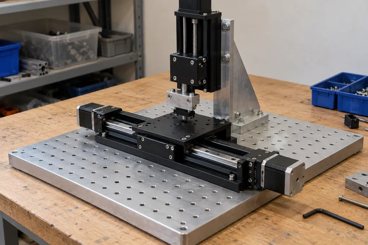
Choosing XY, XZ, XYZ or XYθ from the required degrees of freedom
Translate the task into independent motion directions, then choose XY, XZ, XYZ or XYθ with explicit axis definitions and per-axis travel requirements.
Selection guide · 4 min read ·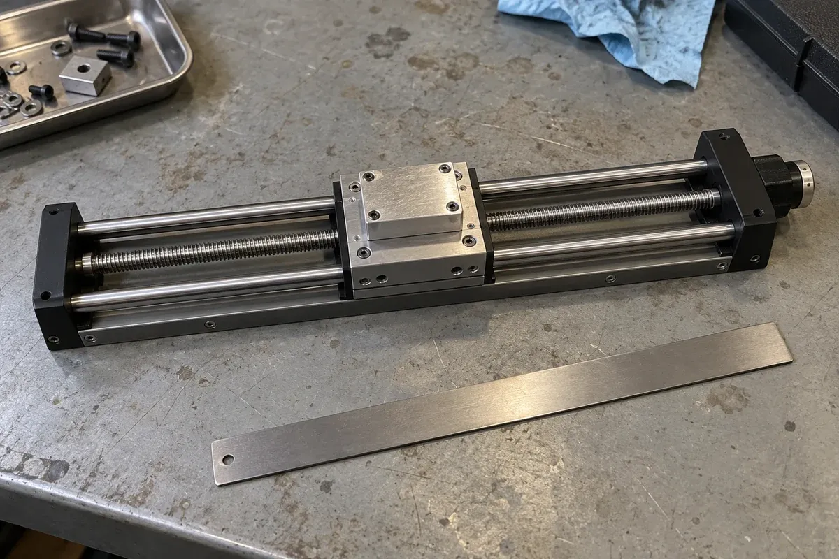
Stage Selection & Buying Guides
Comparing screw, linear-motor, piezo, flexure and air-bearing stages
Compare stage actuation, guidance, feedback and support separately, then request configuration-specific evidence for the intended movement and load.
Selection guide · 8 min read ·From requirements to a quotation
Review your stage requirements
Share the motion envelope, payload, orientation and acceptance criteria. Request confirmation of the exact configuration before ordering.
Request a Quote