Key takeaways
- Select angular stops from visible features rather than an arbitrary division of a circle.
- Separate part registration from the rotary mechanism reference.
- A camera trigger needs a verified relationship to the intended pose.
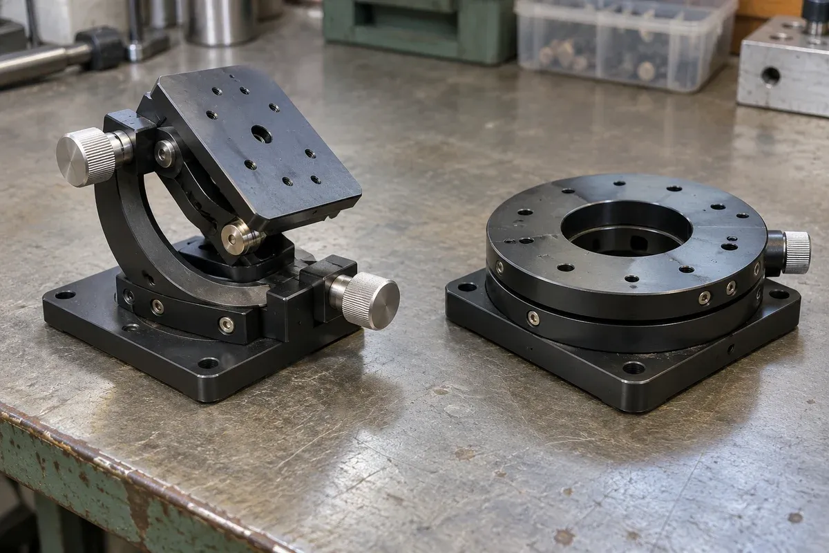
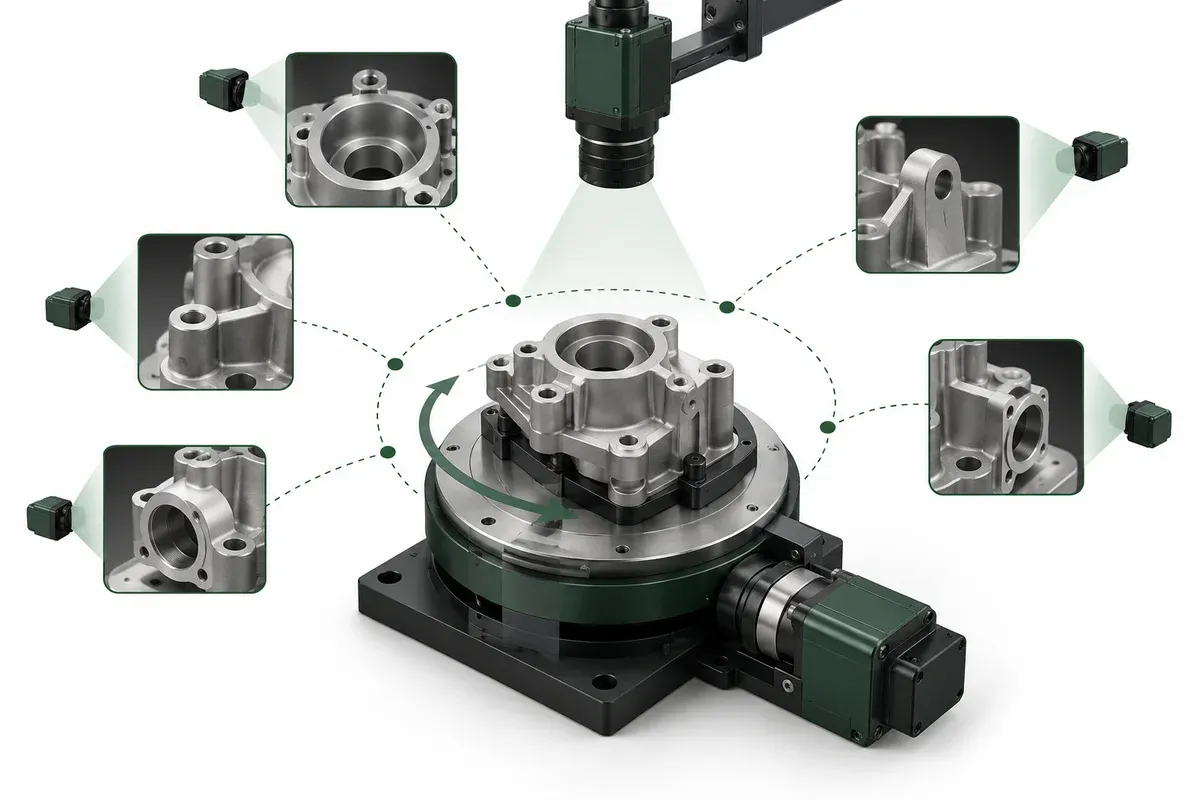
Rotary indexing for camera inspection is a coordination problem. The part must be presented in meaningful views, the camera must acquire at the correct time and the resulting image must stay linked to the correct part and angle. A stage that rotates successfully satisfies only one piece of that sequence.
This article offers a prospective inspection-planning worksheet. It does not claim validated defect detection, inspection accuracy, throughput or yield for any catalogue model.
Choose views from the inspection question
Begin with the features that must be observed. Mark them on a part drawing and identify which viewing directions make them accessible to the camera and illumination. A uniform set of angles may be convenient, but convenience does not prove coverage.
Ask the vision owner to distinguish simple presence checks from dimensional measurements or subtle defect decisions. Each requires its own evidence. If a critical surface is hidden by the fixture, adding more rotary stops may not solve the obstruction.
Record whether images are taken at discrete stops or during motion. This brief concerns indexed acquisition; continuous acquisition introduces additional timing and motion requirements that must not be assumed from a static demonstration.
Establish part registration independently
Define how the part sits in the holder and how its angular reference relates to the rotary axis. A machine home signal identifies a mechanism reference, not necessarily a feature on a newly loaded part.
Include the holder’s centering and retention method in the drawing package. If the part is intentionally eccentric, state that explicitly. Offsets affect both the swept envelope and what the camera sees at different angles.
Zaber’s Keyence integration guide illustrates a third-party system combining a rotating workpiece with optical inspection hardware. Its specified integration is evidence about that arrangement, not a claim of equivalent inspection capability for other stages.
Make the acquisition handshake explicit
For each view, identify the requested angle, the controller state used to permit acquisition and the camera acknowledgement that confirms a usable frame. Record the exact meaning of each signal from the relevant equipment documentation.
Give images identifiers containing the part record and view identity. Store the intended angle and available position evidence separately. If an image is missing, ambiguous or rejected, preserve that outcome rather than shift all later images into earlier positions in the sequence.
Define recovery from interruption before conducting a long trial. The system needs a clear decision about whether it can resume a known view, repeat the part or require re-registration. That choice affects traceability as much as mechanics.
Practical indexed-inspection checklist
- List every required feature and the view that exposes it.
- Document the part datum, holder reference and rotary-axis relationship.
- Check the part and cable swept envelopes at all proposed stops.
- Specify readiness, trigger, acknowledgement and image-validity signals.
- Associate each image with a part, view and configuration record.
- Define missing-frame handling without silently reassigning view labels.
- Establish a coverage trial and a separate motion verification trial.
Include lighting state when it changes between views. A correct angle under the wrong illumination can produce an unusable image even when the controller reports a normal sequence.
Hypothetical example: six stops with one hidden feature
Suppose a concept fixture divides a rotation into six equal views. A drawing review reveals that the clamp covers a required edge in every view. The proposed solution is not to claim that a finer indexing interval improves coverage; the fixture or viewing arrangement must change.
After that change, the team retains six stops only if the vision review shows that they expose the required features. These are hypothetical design decisions, not evidence that six views are sufficient for any real part.
Define acceptance beyond movement
A complete trial should establish view coverage, consistent part registration, correct image association and the inspection method’s own acceptance performance. Use rotary stage pages for initial mechanical comparison, then confirm the exact configuration and interfaces. Motion repeatability alone cannot establish whether the camera system sees or correctly classifies the feature of interest.
Include representative parts with the expected variation in seating and surface appearance when evaluating whether the selected viewpoints remain useful.
Questions
Does four-view inspection cover a whole part?
Only if the required features are demonstrably visible and measurable in those views; coverage must be established from geometry and trials.
Is the rotary home position the part datum?
Not automatically. The fixture must establish or measure the part orientation relative to the mechanism reference.
Can a missed image be silently replaced by the next image?
No. Preserve the view identity and handle a missing acquisition explicitly so results remain associated with the correct pose.
Sources & scope
Sources support the specific points described below. General engineering guidance and third-party examples do not establish a catalogue model's performance or suitability.
- Zaber: Automating Workpiece Rotation for Keyence TM-X Inspection
Third-party integration example linking a rotary workpiece fixture to an optical inspection system; no inspection performance transfer.
Accessed
Related engineering resources
Continue reading
Applications & System Design
Planning a hollow-rotary fixture with central cable or optical access
Plan a hollow-rotary inspection fixture around usable aperture, optical access and cable routing, without assuming unrestricted rotation.
Application guide · 4 min read ·
Applications & System Design
Field-of-view calculator and calibration for stage motion
Use the field-of-view calculator for camera and microscope coverage, check calibration and turn the usable field into a stage-motion brief.
Application guide · 8 min read ·From requirements to a quotation
Review your stage requirements
Share the motion envelope, payload, orientation and acceptance criteria. Request confirmation of the exact configuration before ordering.
Request a Quote