Key takeaways
- The usable opening is the smallest opening through the complete fixture.
- A central hole does not eliminate cable twist.
- Check sight lines and swept volumes throughout the intended angular sequence.
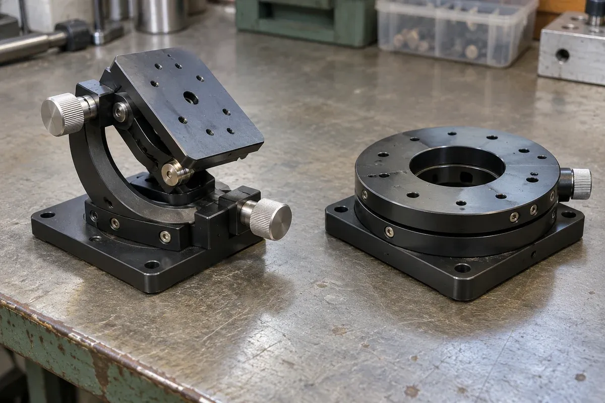
A hollow rotary table can make central access possible, but the aperture solves only a geometrical part of the fixture. The holder, mounting adapter, cables and inspection optics all compete for the same space. A useful concept drawing therefore treats the central opening as an access corridor through an assembly, not an isolated catalogue dimension.
This is a prospective inspection-fixture review. It does not establish a proven application, unlimited rotation or optical inspection performance for catalogue hollow rotary products.
Draw the complete access corridor
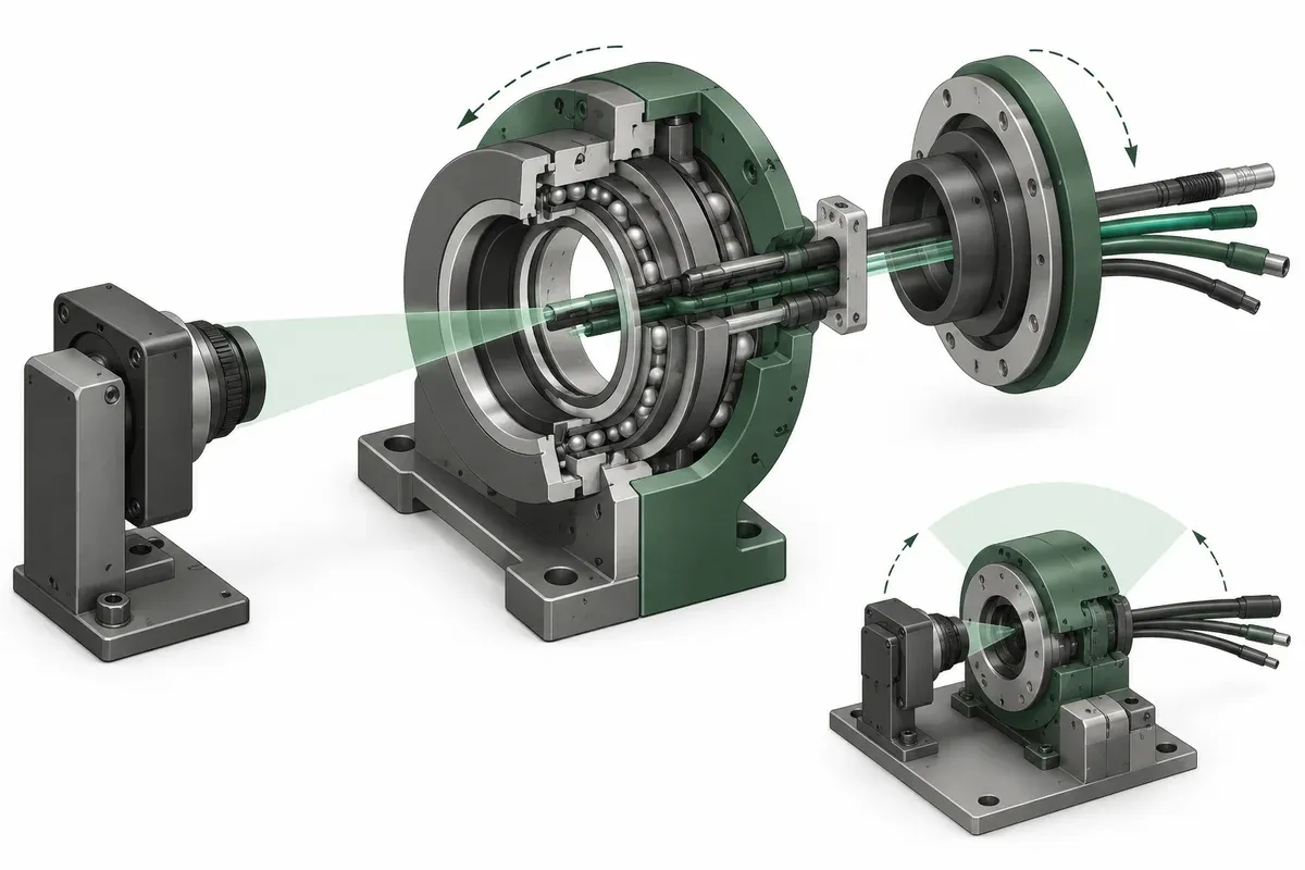
Start with a section through the base, table, adapter and part holder. Mark every opening and any object that enters it. The limiting aperture may belong to an adapter or clamp rather than the rotary mechanism.
If the purpose is optical access, draw the required viewing or illumination envelope, not only a centerline. Include the relevant field of view and positions that must remain unobstructed. Ask the imaging owner to establish what clear space is required for the intended inspection.
Zaber’s rotary-stage selection guide discusses central access as a selection consideration. It does not establish that another mechanism’s opening, load capacity or routing arrangement meets this fixture’s needs.
Decide what rotates and what stays fixed
Label every cable, optical element and service connection as rotating or stationary. Then follow the relative motion through the planned angular sequence. A cable passing through the center can still twist if one end rotates and the other does not.
Specify the required angular history, including return movements and repeated cycles. A one-time sweep and repeated same-direction turns impose different routing questions. Do not infer unrestricted service rotation from a table’s ability to turn through a full circle.
If a rotary connection is proposed, obtain its exact suitability and interface evidence from its supplier. Do not assume a generic slip ring or optical rotary joint is compatible with the signal, environment or measurement requirement.
Keep inspection geometry separate from mechanical reach
Zaber’s workpiece-inspection integration example illustrates the need to integrate the rotating fixture and the optical measurement arrangement. Its inspection system is a third-party reference, not validation of a hollow-table concept in this catalogue.
Check whether the part remains within the camera’s useful view at every required stop. Include eccentric features and the holder’s swept envelope. An unobstructed center at zero angle does not guarantee unobstructed views elsewhere.
Review the fixture’s load offsets and moments with the exact configuration drawing. The aperture may tempt a tall or overhanging bracket that needs separate mechanical evaluation. Do not judge suitability from axial payload alone.
Practical central-access checklist
- Draw a section through every layer of the central corridor.
- Mark the minimum unobstructed opening after adapters and services are installed.
- Label rotating and stationary components and their connections.
- Specify the angular sequence, return direction and repeated-cycle behavior.
- Check sight lines, camera coverage and swept envelopes at all required poses.
- Request configuration-specific load and moment evidence.
- Define an assembled-fixture inspection before any process qualification claim.
Include maintenance access. A cable or optical component that can be installed only before the table is assembled may create a service problem even when the geometry fits on paper.
Hypothetical example: the adapter becomes the bottleneck
Imagine a concept table selected for its large center opening. The proposed part holder uses an adapter plate with a smaller aperture, and a cable clamp projects into the remaining optical corridor. The table itself meets the original bore requirement, but the assembly does not provide the intended sight line.
The design review revises the complete access drawing and checks the resulting structure and routing again. This invented example does not recommend an aperture size or demonstrate a successful inspection result. It shows why the requirement must apply to the assembled corridor.
Request a configuration review, not a bore comparison
Use hollow rotary listings to identify candidate layouts, then provide the section drawing, routing plan and angular sequence to the relevant suppliers. Acceptance should verify clear access and correct service behavior through the complete sequence. Catalogue geometry is a starting input; it is not proof that the installed fixture preserves the required optical or cable path.
Questions
Does a hollow table permit unlimited cable rotation?
No. Routing through an aperture does not remove twist; the allowed sequence and any rotary connection need separate design verification.
Is the catalogue bore the usable optical aperture?
Not necessarily. Adapters, fixtures, fasteners and cables can reduce or obstruct the complete opening.
Can the opening serve both optics and cables?
Possibly, but the combined envelopes, motion and sight lines must be checked in the actual assembly.
Sources & scope
Sources support the specific points described below. General engineering guidance and third-party examples do not establish a catalogue model's performance or suitability.
- Zaber: Selecting a Motorized Rotary Stage
Primary rotary-stage selection discussion covers geometry, load and central access as configuration questions.
Accessed - Zaber: Automating Workpiece Rotation for Keyence TM-X Inspection
Third-party integration example linking a rotary workpiece fixture to an optical inspection system; no inspection performance transfer.
Accessed
Related engineering resources
Continue reading
Applications & System Design
Defining a rotary indexing sequence for camera-based part inspection
Build a rotary inspection brief around required camera views, part references, indexed stops and acquisition evidence, without assuming inspection yield.
Application guide · 4 min read ·
Applications & System Design
Field-of-view calculator and calibration for stage motion
Use the field-of-view calculator for camera and microscope coverage, check calibration and turn the usable field into a stage-motion brief.
Application guide · 8 min read ·From requirements to a quotation
Review your stage requirements
Share the motion envelope, payload, orientation and acceptance criteria. Request confirmation of the exact configuration before ordering.
Request a Quote