Key takeaways
- Focus quality must be judged optically, not by motor step count alone.
- Keep the imaging range separate from loading and objective clearance.
- Record approach direction, image identity and the actual configuration.
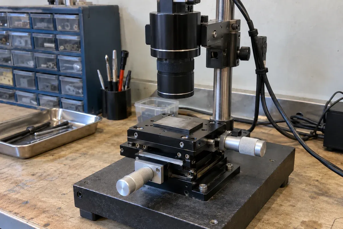
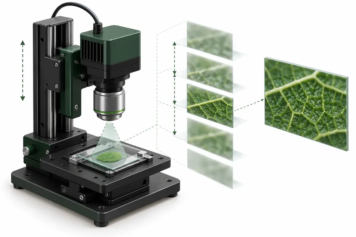
A repeatable focus sequence needs more than a list of Z coordinates. The bench must keep the objective and sample clear of one another, associate images with the intended planes and distinguish optical sharpness from mechanical positioning performance. The best requirements package shows how all three will be checked.
The discussion here is a proposed benchtop evaluation method. It does not establish compatibility with a microscope, suitability for clinical use or a guaranteed focus performance for catalogue stages.
Define the optical result first
Specify whether the task is to return to one focal plane, capture a stack or search for an acceptable focus condition. These tasks can require different motion sequences and different evidence.
Nikon’s explanation of depth of field and depth of focus provides the optical context for focus tolerance. The motion brief should reference the imaging team’s criterion rather than equate a motor increment with the depth of field.
Choose a representative sample and a repeatable image-quality assessment. Record which region of the image matters. A focus measure optimized for one feature may not represent a differently textured or tilted part of the specimen. Identify that limitation before automating decisions around it.
Separate imaging motion from clearance
Draw the closest permissible relationship between objective, sample and holder as determined by the responsible designer. Show the complete specimen envelope, including covers, clamps and features that may protrude beyond the nominal imaging plane.
The allowable imaging range is not the same as the stage’s full mechanical travel. Define separate loading, inspection and recovery positions where appropriate. If a sample or objective can be changed, specify how the configuration is recognized before the original sequence is reused.
Evaluate the consequences of power loss or an interrupted move with the equipment designer. Do not presume that a vertical load is safely held because a mechanism remains stationary during an ordinary test. Obtain condition-specific evidence for the selected assembly and its controls.
Describe how a plane becomes an image record
For each image, retain a plane identifier, requested coordinate, available position evidence, acquisition condition and validity state. If only commanded position is known, use that label rather than “measured Z.”
Define the readiness condition that permits acquisition. A successful command transmission is not enough to establish that the intended image plane has been reached and is stable for the chosen imaging criterion. The exact handshake depends on the verified controller and camera interfaces.
Record approach direction when it is relevant to the evaluation. Comparing repeated stacks should not silently mix different approach conventions and then attribute every difference to the optics.
Practical focus-sequence checklist
- Identify whether the goal is autofocus, plane return or stack acquisition.
- Record objective, sample holder and imaging configuration revisions.
- Mark the approved imaging range and independently reviewed clearance envelope.
- Define plane spacing as a test requirement, not an assumed achieved movement.
- Specify the move-to-acquire readiness signal and image naming rule.
- Retain rejected images and the reason for rejection.
- State how interruptions, objective changes and unknown sample heights are handled.
The checklist should be completed jointly by imaging and mechanical owners. Neither a camera-only review nor a stage-only review can establish the whole sequence.
Hypothetical example: identical commands, different sample holders
Imagine a team evaluating repeated focus stacks on a flat reference target. It later introduces a taller holder and proposes to reuse the saved coordinate list unchanged. The original image sequence may still be valid as data, but the clearance assumptions and focal reference now require review.
The team creates a holder-specific configuration record, re-establishes the reference plane and verifies the permitted range before evaluating repeatability again. No travel, step size or clearance value is prescribed here; those values belong to the actual optical and mechanical design.
Judge mechanics and imaging separately
Use the resulting images to assess the imaging task, and independent position evidence where needed to assess the mechanism. Vertical lift listings can help compare candidate layouts, but orientation, holding behavior, mounting and controller compatibility remain configuration-specific questions. A sharp stack is useful evidence about images, not a substitute for an axis acceptance test.
Questions
Is the smallest commanded Z increment the best focus step?
Not necessarily. The optical task and demonstrated movement determine useful spacing; an addressable increment is not proof of a distinct focal plane.
Should the objective or the sample move?
Evaluate both layouts against clearance, supported mass, cable routing and the microscope interfaces.
Does a focus-stack image prove Z-axis accuracy?
No. A visually useful reconstruction does not independently measure the physical positions of its source planes.
Sources & scope
Sources support the specific points described below. General engineering guidance and third-party examples do not establish a catalogue model's performance or suitability.
- Nikon MicroscopyU: Depth of Field and Depth of Focus
Explains the optical meaning of depth of field; supports separating focus criteria from mechanical increments.
Accessed - Micro-Manager: MicroMagellan
Documents image tile overlap and Z-step choices in microscope acquisition; does not establish catalogue compatibility.
Accessed
Related engineering resources
Continue reading
Applications & System Design
Field-of-view calculator and calibration for stage motion
Use the field-of-view calculator for camera and microscope coverage, check calibration and turn the usable field into a stage-motion brief.
Application guide · 8 min read ·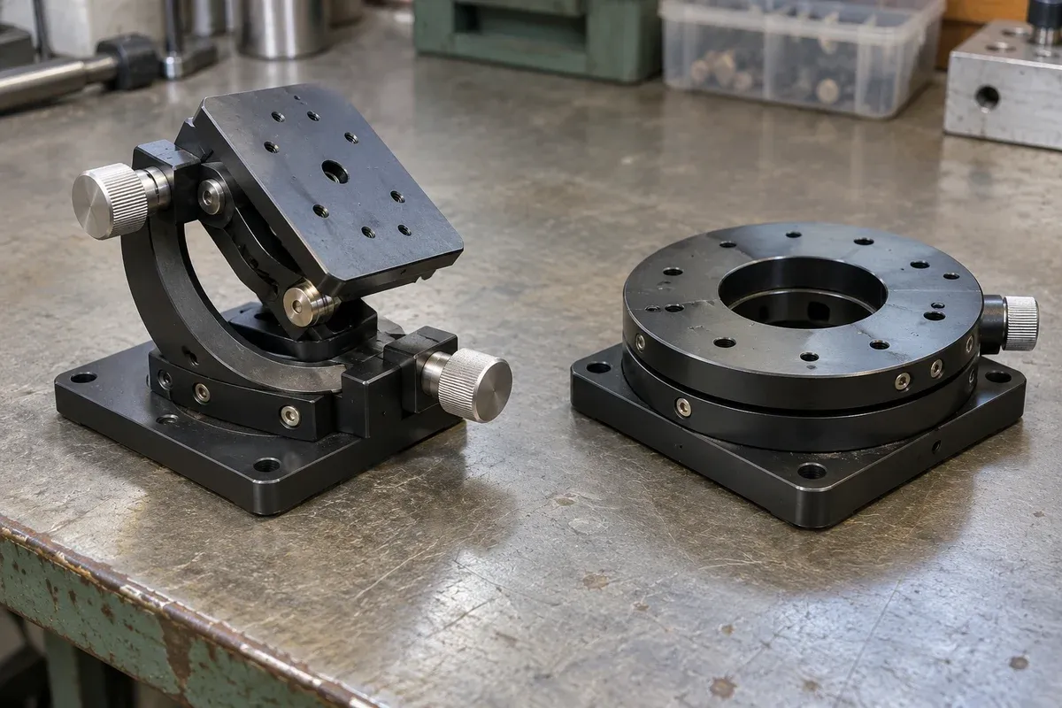
Applications & System Design
Defining a rotary indexing sequence for camera-based part inspection
Build a rotary inspection brief around required camera views, part references, indexed stops and acquisition evidence, without assuming inspection yield.
Application guide · 4 min read ·From requirements to a quotation
Review your stage requirements
Share the motion envelope, payload, orientation and acceptance criteria. Request confirmation of the exact configuration before ordering.
Request a Quote