Key takeaways
- Deposit location and deposited material are separate acceptance questions.
- Include nozzle access, tube forces and maintenance clearance in the motion sketch.
- Fluid and cure parameters require process-owner validation.
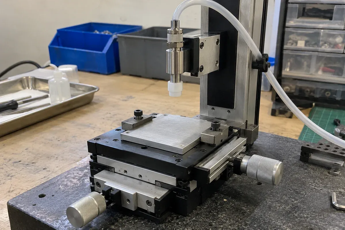
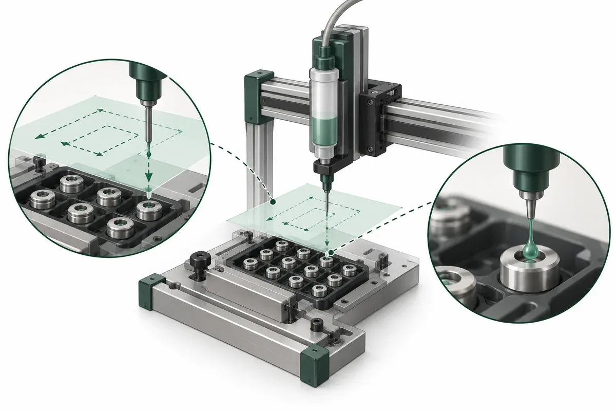
A small-parts dispensing fixture combines a motion task with a material process. The mechanism places a part or nozzle, while the dispensing system determines how material reaches the surface. Combining those responsibilities into one “precision” requirement makes failures harder to diagnose and quotations harder to compare.
The following worksheet is for a proposed fixture evaluation. It does not establish deposit quality, cleanroom compatibility or a validated bonding process for any catalogue stage.
Separate location from deposit acceptance
Define the intended deposition region on the part drawing. Then list the material-result criteria separately, such as the relevant geometry or coverage assessed by the process owner. Avoid assuming that an acceptable nozzle coordinate proves an acceptable deposit.
Nordson EFD’s discussion of thin-fluid dispensing identifies dripping and wicking as fluid/tip issues. The point for motion selection is limited: material behavior needs its own investigation. The reference is not a recipe for the proposed process.
Record which observations distinguish a location problem from a dispensing problem. A camera image, process measurement or other approved check may help, but its acceptance method must be defined before the team interprets trial results.
Choose what moves using the complete assembly
Compare a moving part beneath a fixed nozzle with a moving dispenser above a fixed part. Include holders, adapters, reservoirs where applicable, service tubing and all moving cable restraints. The bare nozzle mass is rarely a complete representation of the moving assembly.
Draw tubing routes at the extremes of motion and at any maintenance position. Ask whether changing fill state or routing changes the mechanical load. These questions require configuration-specific answers; do not convert a horizontal catalogue load directly into evidence for an offset or vertical installation.
Show how operators replace the tip and load or remove parts. A mechanism that reaches every deposit location can still be impractical if the fixture blocks inspection or routine maintenance.
Define sequence boundaries without inventing a recipe
Describe the logical states: part located, motion ready, dispensing permitted, dispensing complete and clearance established. Assign each state a verified signal or observation from the chosen equipment.
The process owner must specify material preparation, dispensing settings, cure requirements and protective measures. This motion brief records their consequences, such as access space or the need to preserve a pose. It does not supply chemical handling instructions, pressure settings or cure exposure values.
Decide what happens to an interrupted part. If the team cannot establish whether material was deposited, restarting the motion sequence may create an unacceptable duplicate deposit. That disposition belongs in the process plan rather than an improvised software retry.
Practical dispensing-fixture checklist
- Mark the deposit region and the separate material acceptance criteria.
- Identify the moving assembly and its changing service loads.
- Show nozzle, holder, tube and maintenance clearances.
- Define the ready, dispense and complete handshakes using actual interface documentation.
- Record tip replacement and part-location verification requirements.
- Specify interruption handling and the disposition of uncertain deposits.
- Plan trials that distinguish positioning variation from material variation.
Ask for a representative test using the actual fixture and an approved process. A dry movement demonstration can establish reach and sequencing, but not deposit quality.
Hypothetical example: good coordinates, inconsistent dots
Imagine a proposed fixture that returns the nozzle to the same requested points while the deposited shapes vary. The first response is to request a stage with a smaller repeatability figure. A structured review instead asks whether nozzle condition, fluid behavior, substrate condition or pose variation explains the result.
The team creates separate checks for mechanical placement and deposit outcome before deciding what to change. This scenario does not identify a real failure or prescribe fluid adjustments. It shows why a motion upgrade is not an evidence-based response to every dispensing variation.
Write a bounded supplier request
Send the mechanical drawing, payload and service-routing information to the motion supplier, and send the material-result requirements to the dispensing specialist. Use multi-axis assemblies as potential layout options only. Final acceptance must cover the integrated fixture and the qualified dispensing process; a catalogue stage rating cannot certify the deposited material or its subsequent attachment behavior.
Questions
Does accurate XY positioning guarantee a consistent deposit?
No. Fluid properties, dispenser behavior, tip geometry and the substrate process require separate control and validation.
Should the nozzle or the part move?
Compare complete moving loads, hose routing, access and fixture constraints; neither architecture is universally preferable.
Can this guide set dispense pressure or cure conditions?
No. Those settings must come from the qualified process owner and applicable equipment and material instructions.
Sources & scope
Sources support the specific points described below. General engineering guidance and third-party examples do not establish a catalogue model's performance or suitability.
- Nordson EFD: Dispensing Tips for Thin Fluids
Identifies dripping, wicking and fluid/tip interactions as dispensing-process issues; no fluid recipe or catalogue-stage claim.
Accessed
Related engineering resources
Continue reading
Applications & System Design
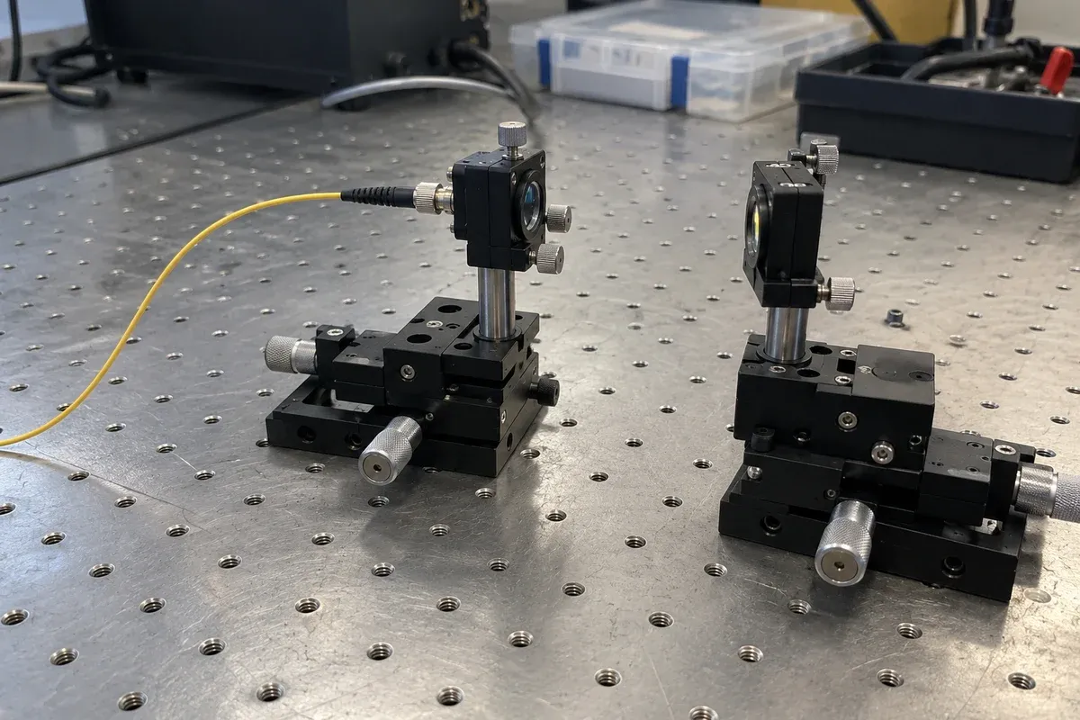
Building a positioning brief for an optical-power search experiment
Define a bounded optical-power search experiment with measurement validity, pose association and stop criteria before specifying motion hardware.
Application guide · 4 min read ·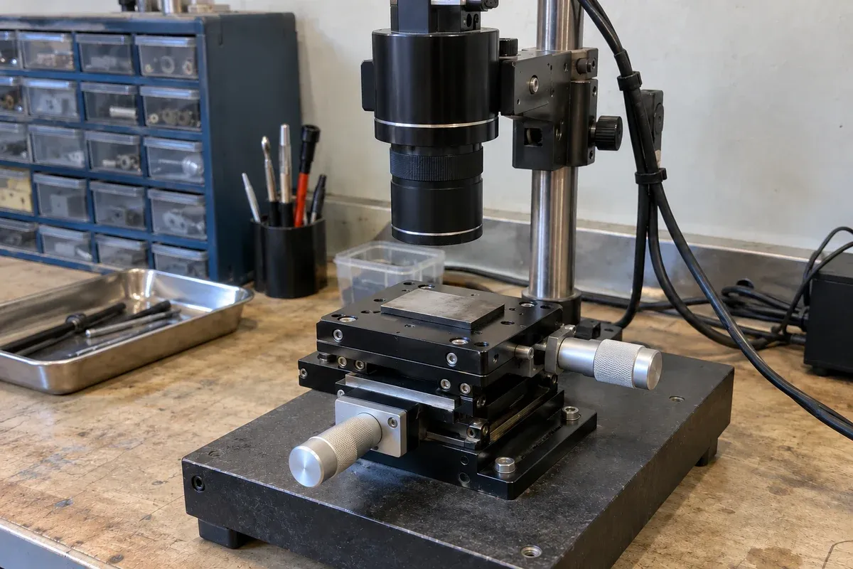
Applications & System Design
Field-of-view calculator and calibration for stage motion
Use the field-of-view calculator for camera and microscope coverage, check calibration and turn the usable field into a stage-motion brief.
Application guide · 8 min read ·From requirements to a quotation
Review your stage requirements
Share the motion envelope, payload, orientation and acceptance criteria. Request confirmation of the exact configuration before ordering.
Request a Quote