Key takeaways
- A fixture needs a named physical reference, not only axis labels.
- Separate mechanical datums from controller home positions.
- Verify relationships at the functional point of the assembled fixture.
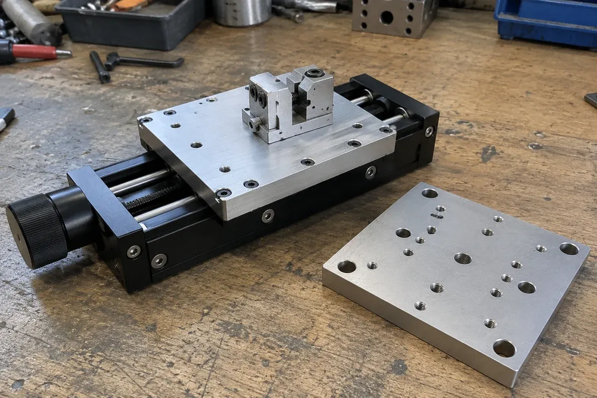
When two engineers describe the same fixture as square, they may be referring to different things. One means the stages are square to each other; the other means motion is square to the part nest. Both descriptions can be internally consistent while the assembled process is misaligned. Defining a common reference before stacking axes avoids this ambiguity.
Choose the reference that serves the task
Identify what the fixture must position relative to: a part nest, inspection plane, optical axis or another physical feature. Then choose reference surfaces or features that establish that relationship. The best reference is not automatically the most convenient outside edge of the baseplate.
Record the selected features on a drawing and describe why they matter. If a machined edge is only cosmetic, it should not become an alignment reference because it is easy to reach. Conversely, a functional reference hidden by the final assembly needs a plan for how its relationship will be established and checked.
The multi-axis accuracy guide identifies the importance of a global reference when evaluating assembled alignment. That principle supports defining references explicitly; it does not supply an acceptance tolerance for a particular fixture.
Separate physical features from coordinate labels
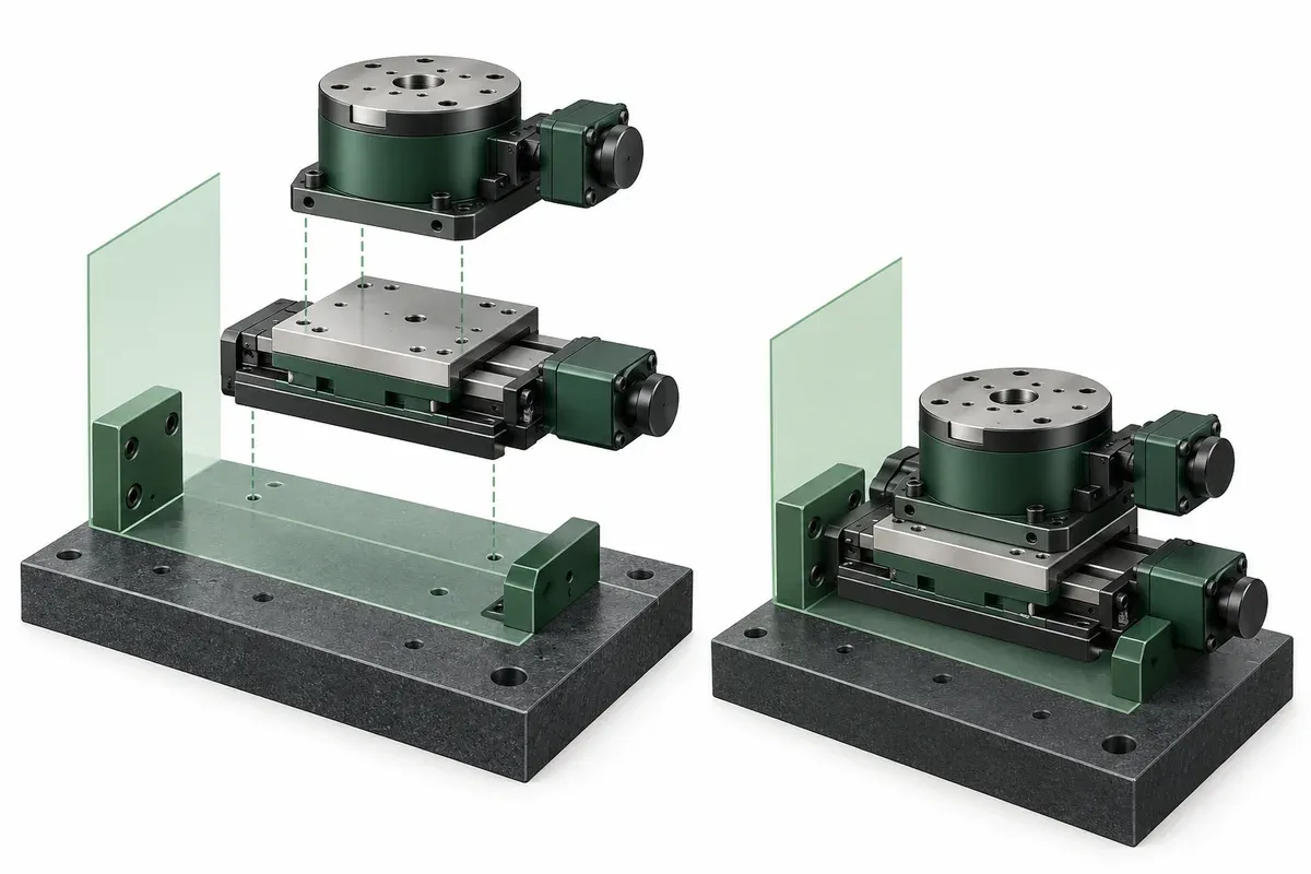
Mechanical datums describe how the assembly is located and related. Motion coordinates describe positions and directions used by the control system. Controller home, software zero and the part’s working origin may all differ. Give each a distinct name in the documentation.
Draw the positive direction of each axis on an assembly view. Show the orientation from the operator’s normal viewpoint and include an unmistakable fixed feature so the view cannot be interpreted backwards. If a stage is installed in a rotated orientation, update the coordinate map rather than relying on its catalogue axis name.
A useful record names the physical reference, the associated coordinate direction, the origin convention and the person responsible for maintaining that definition. This connects the mechanical drawing to later controls and measurement work without pretending that a software offset establishes mechanical alignment.
Plan the reference chain through the stack
For each component, identify what locates it relative to the component below. A clamped interface with clearance holes is different from one with explicitly designed locating features. Do not assume a bolt pattern provides a repeatable datum unless the interface design and evidence establish that function.
Trace the reference chain from the base to the workpiece. Include adapter plates, brackets and removable nests. Ask which relationships can change during servicing and which must be reverified after a component is removed. The resulting chain helps distinguish a stage issue from a fixture-location issue when troubleshooting later.
Datum review checklist
- Name the task reference and identify it on the assembly drawing.
- Show axis directions and the viewpoint used to describe them.
- Distinguish home, software zero and part origin.
- Identify locating features separately from clamping features.
- Trace the reference path through every adapter and bracket.
- Reserve access for the planned reference measurements.
- Define which changes invalidate the recorded alignment.
Agree the required relationships and verification method before discussing numerical acceptance. The tolerance should follow the process requirement and measurement capability, with qualified review. A generic blog example cannot determine how square or parallel your machine must be.
Hypothetical example: a crossed-axis inspection fixture
Consider an inspection fixture with an X stage beneath a Y stage and a removable part nest on top. The initial drawing labels the outer baseplate edge as X. The inspection software instead interprets X along a locating feature in the nest. Those features were never related by a controlled drawing requirement.
The team defines the nest reference, documents its relationship to the base and adds a check after nest replacement. It does not rename the controller axes and assume the geometry is fixed. This fictional situation shows why datum ownership should be resolved before assembly rather than during image-analysis troubleshooting.
The multi-axis catalogue describes available arrangements. For a selected configuration, request the applicable assembly and alignment evidence and connect it to your own datum plan. A component specification and a complete fixture reference chain answer different questions.
Questions
Is the home switch a mechanical datum?
It can provide a motion reference, but it does not by itself define the fixture support plane or the part-location features.
Must the baseplate always be the reference?
No. Choose a stable, accessible reference tied to the task, and document how the other components relate to it.
Does stacking nominally square stages prove squareness?
No. The assembled relationship requires an appropriate verification plan and agreed acceptance criteria.
Sources & scope
Sources support the specific points described below. General engineering guidance and third-party examples do not establish a catalogue model's performance or suitability.
- Zaber multi-axis accuracy guide
Supports the narrow general principles that reference frames, assembly alignment and tool-point offsets matter; no system performance is inferred.
Accessed
Related engineering resources
Continue reading
Mounting & Mechanical Integration
Checking the support surface before installing a precision stage
Organize a support-surface readiness review around documented requirements, contact geometry, surface condition and traceable inspection evidence.
Integration guide · 4 min read ·
Mounting & Mechanical Integration
Choosing the order of an XYZ stack
Compare XYZ stack arrangements through moving mass, payload offsets, working height and access before selecting a mechanical layout.
Integration guide · 4 min read ·From requirements to a quotation
Review your stage requirements
Share the motion envelope, payload, orientation and acceptance criteria. Request confirmation of the exact configuration before ordering.
Request a Quote