Key takeaways
- Locate the desired pivot before selecting an angular-motion family.
- Include adapters and fixture height when checking the work-point position.
- Compare the complete swept geometry and loading, not only the angle range.
Define what must rotate and what must stay put
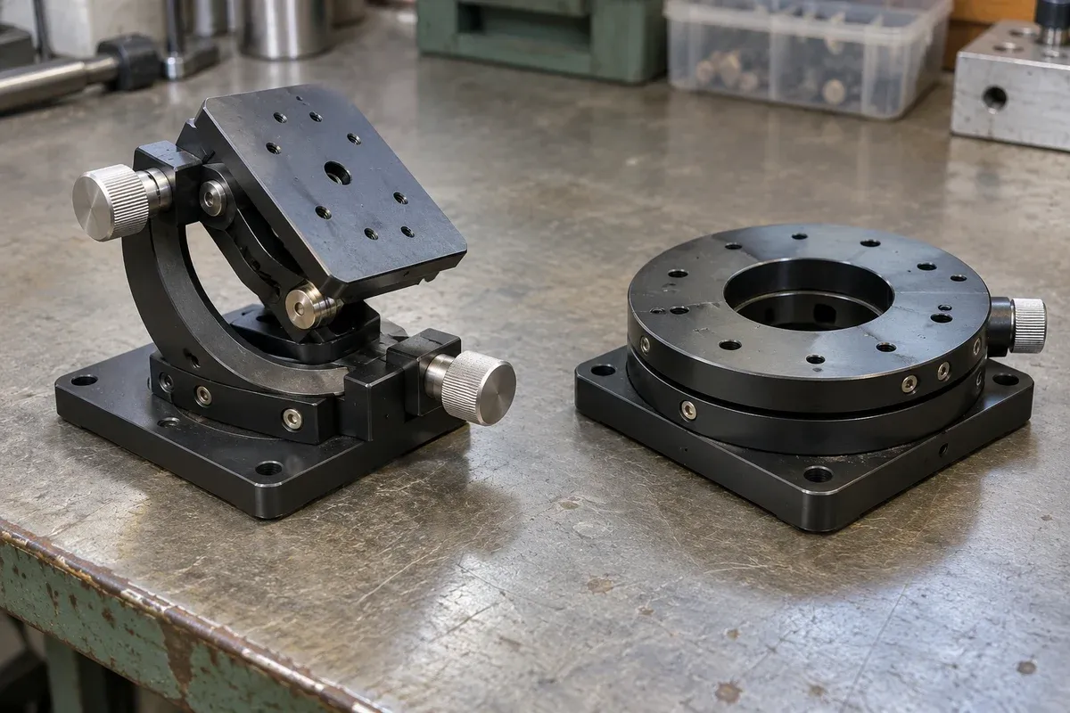
“Add tilt adjustment” is not yet a complete mechanical requirement. Identify the workpiece feature whose orientation needs to change and the point or line that should remain in place. Then draw the desired rotation axis through the fixture. This simple sketch often separates a goniometer problem from a rotary-table problem before any performance figures are considered.
The goniometer family describes arc motion about a center above the table. The rotary-stage family provides rotation about the stage’s own axis. Either can be part of an angular adjustment system, but their geometry is not interchangeable merely because both use degrees.
Specify the angular requirements behind tip and tilt
Edmund Optics lists a micrometer-driven example with two tilt axes.
Specify each required independent angular axis and its direction, the useful pivot location, and the permitted movement of the work point during adjustment. Is one axis sufficient, or must two be adjusted independently? Request an assembly drawing showing how adapters and added axes affect the pivot and work-point path. A name such as tip/tilt, goniometer or rotary stage does not establish the assembled geometry or compatibility with our catalogue models.
Locate the work point relative to the proposed axis
Mark the work point on a side view and measure its location from the reference surface used in the candidate drawing. Include the adapter, clamp and workpiece dimensions. A rotation-center height is meaningful only when its starting surface is understood; a height measured from the base and one measured from the moving table are different quantities.
In a hypothetical optical fixture, the feature to be aligned sits 40 mm above the moving mounting surface. A proposed goniometer drawing places its nominal rotation center 50 mm above that same surface. The geometry has a 10 mm mismatch before tolerances are considered. That observation does not authorize a particular spacer or establish a final design, but it tells the reviewer exactly what must change or be accommodated.
Do not round the mismatch away because the angular range is small. If maintaining the feature position matters, evaluate the path over the required angles. If some translation is acceptable, specify that tolerance as part of the task.
Trace the complete angular envelope
Place the fixture at both angular endpoints and inspect intermediate positions where clearances may be smallest. The feature intended to remain near the pivot is only one part of the assembly. Clamps, cables and projecting workpiece edges still move through space.
For a rotary-stage arrangement, identify how the fixture locates the desired axis relative to the table. For a goniometer arrangement, show how the feature is placed at the intended center. Neither route eliminates the need for an installed-envelope review. Include access for mounting tools and part replacement while the mechanism is in its approved service position.
If two angular axes are proposed, draw them together. Ask whether the intended axes intersect at the useful work point and what the lower mechanism carries. A separate drawing for each component cannot by itself establish the combined geometry.
Compare angular performance only after geometry fits
Once the pivot arrangement is plausible, list the angular range required for setup, operation and recovery. Distinguish angular positioning accuracy, repeatability and backlash rather than using whichever catalogue number appears smallest. The site specification guide provides the general distinction between command resolution, return behavior and positioning accuracy.
Also ask for the loading basis in the intended orientation. Show the fixture and center of mass at the relevant angular positions. A candidate with suitable nominal range may still need an application-specific load review. Keep unsupported fields open rather than borrowing a capacity from another installation.
Use a pivot-review checklist
A concise review package should answer:
- Which feature must remain at the intended pivot?
- What reference surface defines rotation-center height?
- What dimensions locate the feature after adapters and clamps are installed?
- What angular endpoints and intermediate clearances matter?
- How do cable routing and loading change with angle?
- Where will the acceptance measurement be made?
This checklist is particularly useful when several people own different parts of the stack. It prevents one person from treating a nominal stage center as the finished fixture center while another is still changing adapter height.
Record the geometry that justified the choice
Conclude the selection with a side-view drawing and an explicit statement of the permitted work-point motion during tilt. Request supplier confirmation against that drawing revision and the proposed configuration. If a later clamp change moves the feature, revisit the pivot geometry before reusing the earlier approval. The strongest reason to choose a goniometer or rotary arrangement is that its verified motion matches the task, not that one category sounds more precise.
Questions
What distinguishes a goniometer from a rotary stage?
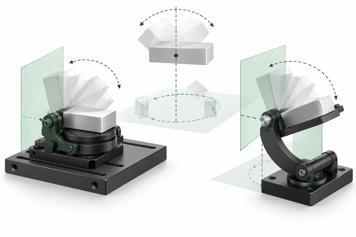
The goniometer family on this site moves through an arc about a center above the table. A rotary-stage layout turns about its own rotation axis. Match that geometry to the desired workpiece pivot.
Will a goniometer keep every feature stationary during tilt?
No. Only a feature correctly located on the intended rotation axis avoids geometric displacement from that rotation. Other points trace arcs, and real motion errors still require evaluation.
Can I add a spacer to reach the specified rotation center?
A spacer may help position the feature, but its dimensions, mass, mounting and effect on loading require review. Use the actual reference surfaces on the drawing.
Sources & scope
Sources support the specific points described below. General engineering guidance and third-party examples do not establish a catalogue model's performance or suitability.
- Goniometer stages
The family uses an above-table rotation center and publishes model-specific center geometry.
Accessed - Rotary stages
The family contains rotary-axis positioning mechanisms with model-specific angular ranges.
Accessed - How to read the specifications
Definitions and the catalogue, derived and not-confirmed labels used on this site.
Accessed - Edmund Optics tip/tilt example
Third-party example with two tilt axes and micrometer drive.
Accessed
Related engineering resources
Continue reading
Stage Selection & Buying Guides
Comparing screw, linear-motor, piezo, flexure and air-bearing stages
Compare stage actuation, guidance, feedback and support separately, then request configuration-specific evidence for the intended movement and load.
Selection guide · 8 min read ·Stage Selection & Buying Guides
Limited-angle or continuous rotation: specify the required motion
Specify angular range, rotation direction, turn count and cable behavior separately when choosing limited-angle or continuous rotary motion.
Selection guide · 4 min read ·From requirements to a quotation
Review your stage requirements
Share the motion envelope, payload, orientation and acceptance criteria. Request confirmation of the exact configuration before ordering.
Request a Quote