Key takeaways
- Offset and angular motion must be considered together.
- Use radians and consistent length units in small-angle estimates.
- Verify the functional point rather than assuming encoder-location performance transfers unchanged.
Locate the point that actually matters
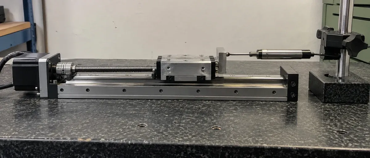
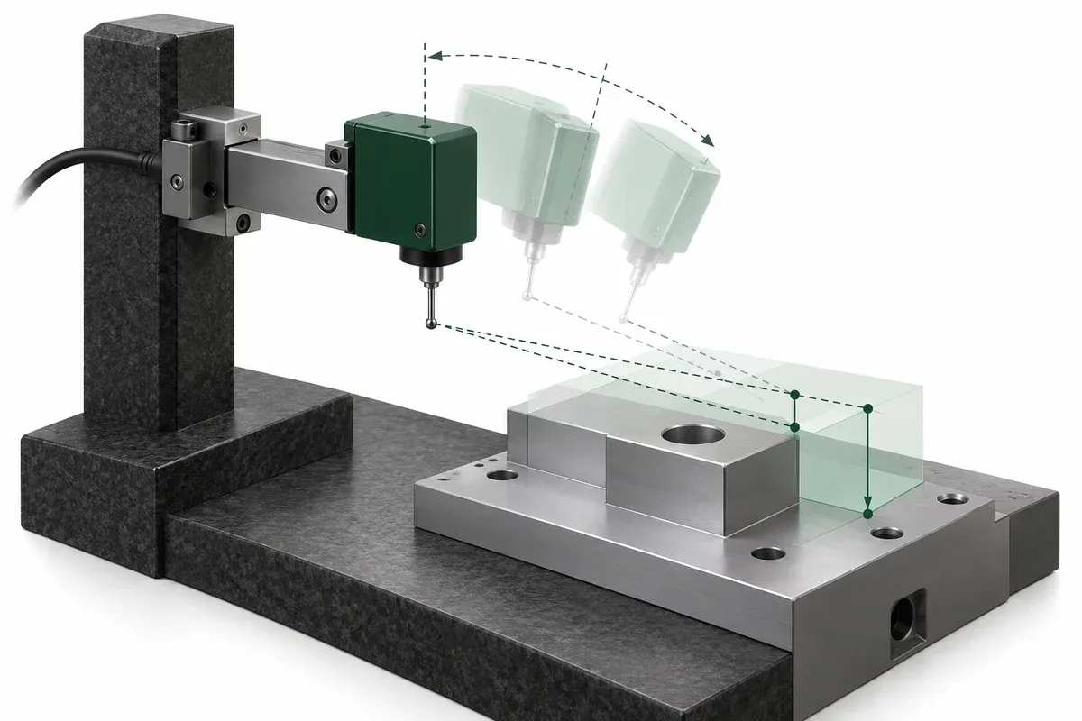
A stage’s feedback system may observe motion on a line different from the point where the process occurs. A camera, nozzle or probe can sit above or beside that line. Before interpreting a positioning specification, mark both locations on the assembly drawing and identify the angular motions that could separate their behavior.
Newport describes the relationship between angular motion and measurement-line offset as Abbe error. The design task is to determine whether that geometry matters for the application. A small feedback increment does not answer the question, and a repeatability figure at one location should not be silently transferred to another.
Make a bounded geometric estimate
For a simple small-angle geometry, the magnitude of a relevant displacement contribution can be approximated by offset multiplied by angular change expressed in radians. The sign and affected coordinate depend on the direction of the offset and the rotation axis. Draw that relationship before using a scalar estimate.
Use consistent units throughout. If the offset is in meters, multiplying by radians gives a displacement in meters. If it is in millimeters, the result is in millimeters. An angle in degrees must be converted first. Record whether the angular input is a signed value, a total range or a plus-or-minus bound so the output preserves the same meaning.
This estimate is not a complete uncertainty budget. It omits other positioning contributions and may not represent coupled three-dimensional motion. Use it to identify sensitive geometry and measurement priorities. For a stacked or articulated assembly, a coordinate transformation may be needed rather than adding several unsigned offsets indiscriminately.
Hypothetical example: a 50 mm offset
Assume, purely for illustration, a relevant perpendicular offset of 50 mm and an angular change of 20 µrad. The small-angle product is 50 mm multiplied by 0.000020, giving 0.001 mm, or 1 µm. These are invented inputs for explaining the calculation. They are not measurements, product ratings or an acceptance threshold.
If the illustrative offset were reduced to 25 mm while the same angular change remained, that particular estimated contribution would halve. This arithmetic does not promise that modifying a real fixture will halve its total error: the modification can also affect loading, stiffness, cables and other geometry. The example supports a design discussion, not a performance claim.
Note that neither the sign nor a peak-to-peak system result follows from the two magnitudes alone. Preserve the actual angular trace and coordinate convention if a detailed error prediction is needed. Converting the example’s 1 µm into an unexplained ±1 µm specification would add information the calculation did not supply.
Plan verification where the process occurs
Whenever practical, arrange an independent measurement at the workpiece’s functional point or along the relevant sensing line. If direct access is impossible, document the surrogate point and the model used to relate it to the workpiece. Include uncertainty in the offset and angular observation rather than treating the drawing dimensions as exact.
Compare the intended payload geometry with the geometry used for any supplier evidence. Ask about sensor height, lateral offset, load and compensation conditions. Zaber’s multi-axis accuracy guide provides system-level context for this review. Its examples do not establish the performance of another manufacturer’s assembled system.
Practical checklist for an offset review
- Mark the feedback line and functional point on the same drawing.
- Identify the rotation axis associated with each offset component.
- Convert angular inputs to radians before a small-angle calculation.
- Preserve signs, units and interval conventions in the worksheet.
- Label estimated contributions separately from measured system results.
- Verify at the functional point or document the surrogate model.
- Revisit the assessment after changing spacers, tooling or payload position.
Keep the calculation with the assembly revision that generated it. Refer to the specification guide for accuracy, repeatability and resolution terminology, then add this geometry-specific evidence to the acceptance plan. The strongest outcome is a clear statement of which point has been verified and under which conditions, rather than a generic claim that the stage is “accurate enough.”
Questions
Does zero Abbe offset eliminate every positioning error?
No. It addresses one geometric contribution; scale, thermal, straightness and other effects can remain.
Can encoder resolution be used as the Abbe error estimate?
No. The estimate needs relevant angular motion and geometric offset, not the encoder increment.
Is offset times angle always sufficient?
It is a small-angle estimate for a specified geometry. Use the appropriate coordinate model when multiple rotations or large angles matter.
Sources & scope
Sources support the specific points described below. General engineering guidance and third-party examples do not establish a catalogue model's performance or suitability.
- Newport: Motion Basics Terminology and Standards
Abbe error links angular motion with offset between measurement and functional lines.
Accessed - Zaber: Multi-Axis Accuracy Guide
System-level accuracy depends on measurement location and geometric error contributions.
Accessed
Related engineering resources
Continue reading
Accuracy & Metrology
Accuracy, repeatability and resolution: three separate acceptance questions
Turn accuracy, repeatability and resolution into separate acceptance requirements, with a worksheet for evidence, conditions and decisions.
Verification guide · 4 min read ·Accuracy & Metrology
Assessing velocity stability and following error during a scan
Plan scan-motion measurements with explicit trajectory definitions, acquisition bandwidth, payload and processing for velocity and following error.
Verification guide · 4 min read ·From requirements to a quotation
Review your stage requirements
Share the motion envelope, payload, orientation and acceptance criteria. Request confirmation of the exact configuration before ordering.
Request a Quote