Key takeaways
- Determine who supports the payload and constrains unwanted motion.
- Evaluate the complete guided mechanism rather than an actuator rating alone.
- Record mechanical and acceptance responsibilities at each interface.
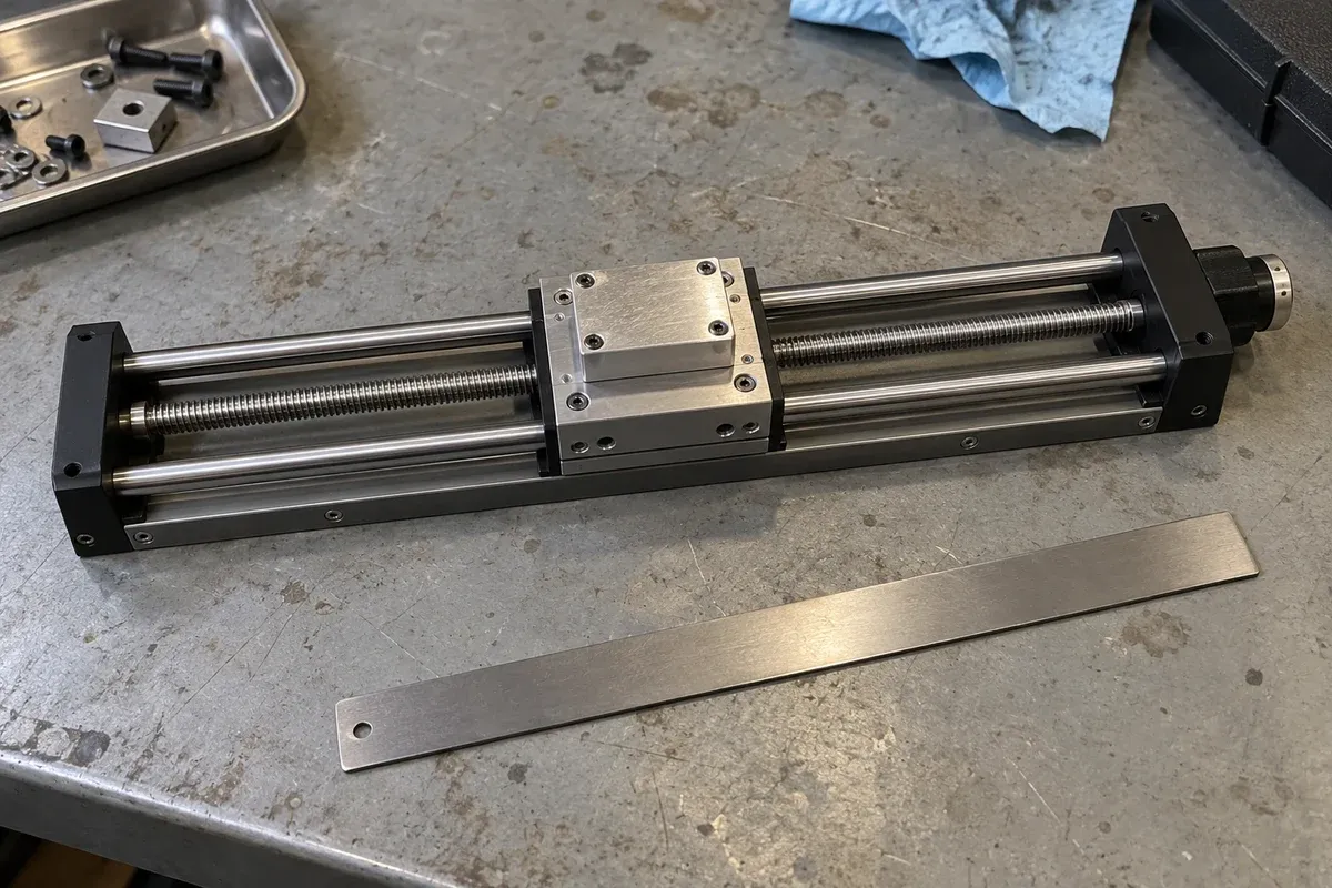
Identify the job hidden inside the word actuator
A buying discussion can go wrong before any dimensions are compared. One person may mean a complete guided positioning platform when saying actuator; another may mean the drive that pushes an existing carriage. Begin by drawing the mechanism you intend to buy and marking which parts already exist. The name on the product category is secondary to the physical boundary of supply.
Zaber describes a linear stage as a device that both provides linear motion and supports transverse forces through its bearings. That is a useful starting distinction, not a universal naming rule. A product sold as an actuator may itself have guidance. Read the drawing and permissible loading description before classifying it.
Inspect the mechanism behind overlapping names
PI notes that some rodless actuators are also called linear stages.
Before choosing by name, ask what guides the moving interface, where the fixture attaches, how transverse loads reach the support, and which parts belong to the quoted supply. Does the drawing show a guided table, an actuator requiring separate guidance, or another arrangement? Record force requirements in newtons (N) and payload information in kilograms (kg) as different quantities. Do not equate them through a simple conversion; loading direction, support and operating conditions still need explicit review.
Trace the load path through the fixture
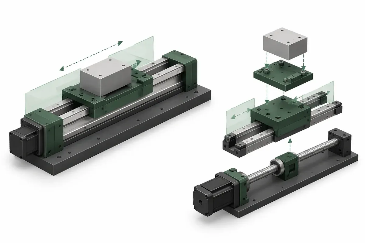
Draw arrows from the workpiece through the clamp, moving platform, bearings and mounting structure. Identify what prevents unwanted pitch, yaw, roll and transverse displacement. If the proposed purchase provides only axial motion, another part of the design must carry and guide the assembly. Do not leave that responsibility implicit.
For a hypothetical fixture, imagine an existing rail-mounted carriage that needs automated approach motion. A separate actuator could be a candidate because guidance is already present. By contrast, a workpiece resting on an unsupported plate needs more than a pushing element. These examples classify the missing function; they do not establish a capacity or recommend a particular product.
Also mark where process forces enter. A probe, clamp or cable can apply force away from the drive line. Ask the supplier to review that geometry, rather than describing the installation only by total mass. The absence of an explicit load limit is a question to resolve, not permission to assume unlimited support.
Inspect the mechanical interface before the performance headline
For a separate drive, identify its output connection, permitted alignment, available mounting adjustment and required support. Ask how the connection accommodates the actual path of the guided carriage. A coupling is part of the mechanism, not merely a way to make two hole patterns meet.
For a complete stage, check whether the mounting surface, moving table and fastener access suit the fixture. Review the moving envelope as well as the stationary footprint. Include the motor, cable exit and any protruding hardware in the space claim. The linear-stage family is a starting point for guided translation candidates; its category description does not replace a model drawing.
A useful interface review asks:
- Which component establishes the motion axis?
- Which component supports transverse and moment loads?
- Where can alignment be adjusted during assembly?
- Who approves the coupling and mounting arrangement?
- What drawing defines the final assembled condition?
Compare performance at the same boundary
An actuator’s displacement capability, a stage’s platform positioning performance and a fixture’s work-point performance describe different objects. Keep those boundaries visible in a comparison. Ask whether a reported value applies to the drive alone, a specified guided assembly, or the delivered system after integration.
For example, do not treat a motor command increment as evidence that a remote sample achieves the same increment. Equally, do not reject a separately guided design simply because its component documentation lacks a complete-system figure. It may require an assembly-level specification and validation plan rather than a different mechanism.
Write an acceptance statement identifying the moving target, measurement reference and assembled configuration. The statement can remain provisional while the supplier reviews feasibility. What matters is preventing a component-level promise from becoming an accidental system-level guarantee.
Make the architecture decision with a responsibility map
Prepare two short supply lists: one for the complete-stage route and one for the separate-drive route. Include guidance, drive, coupling, mounting adapters, controls, assembly work and verification. Mark who supplies and checks each item. The comparison should reveal integration effort and unresolved interfaces without assuming which route costs less.
Choose a candidate architecture when its load path, geometry and responsibilities are coherent. Then request configuration-specific evidence. If an existing guide is poorly documented, measuring or identifying it may be the next useful action. If the fixture has no guidance at all, start with a guided platform or a deliberately engineered guided assembly. Either way, the purchasing decision follows the mechanical task rather than a product label.
Questions
Does every actuator lack guidance?
No. Product terminology varies, and some actuators include guided carriages. Inspect the actual mechanism, permissible loads and drawings rather than relying on the name.
Can an actuator specification describe a complete positioning stage?
Only if the supplier explicitly specifies that assembled configuration. A drive component rating does not automatically cover the guidance, coupling or fixture.
When should I consider a standalone actuator?
When suitable external guidance already exists or the application requires a separately designed guided mechanism. Confirm permissible loading and interface requirements for the proposed actuator.
Sources & scope
Sources support the specific points described below. General engineering guidance and third-party examples do not establish a catalogue model's performance or suitability.
- Motorized linear stages
The listed linear-stage family uses ball-screw drives and includes crossed-roller and linear-ball guideways.
Accessed - Zaber linear-stage selection guide
Defines linear stages as motion devices with bearings that support transverse forces. No Zaber product rating is applied to the catalogue.
Accessed - PI linear actuator terminology
Naming overlap only: some rodless actuators are called linear stages.
Accessed
Related engineering resources
Continue reading
Stage Selection & Buying Guides
Choosing a vertical lift instead of mounting a linear stage vertically
Compare a dedicated vertical lift with a vertically mounted linear stage by checking layout, gravity loading, support and configuration-specific evidence.
Selection guide · 4 min read ·Stage Selection & Buying Guides
Comparing screw, linear-motor, piezo, flexure and air-bearing stages
Compare stage actuation, guidance, feedback and support separately, then request configuration-specific evidence for the intended movement and load.
Selection guide · 8 min read ·From requirements to a quotation
Review your stage requirements
Share the motion envelope, payload, orientation and acceptance criteria. Request confirmation of the exact configuration before ordering.
Request a Quote