Key takeaways
- Angular positioning and axis error motion require distinct evidence.
- A surface runout trace can contain artifact form and mounting effects.
- Record sensing height, radius, orientation and rotation sequence.
Split the rotary requirement into separate questions
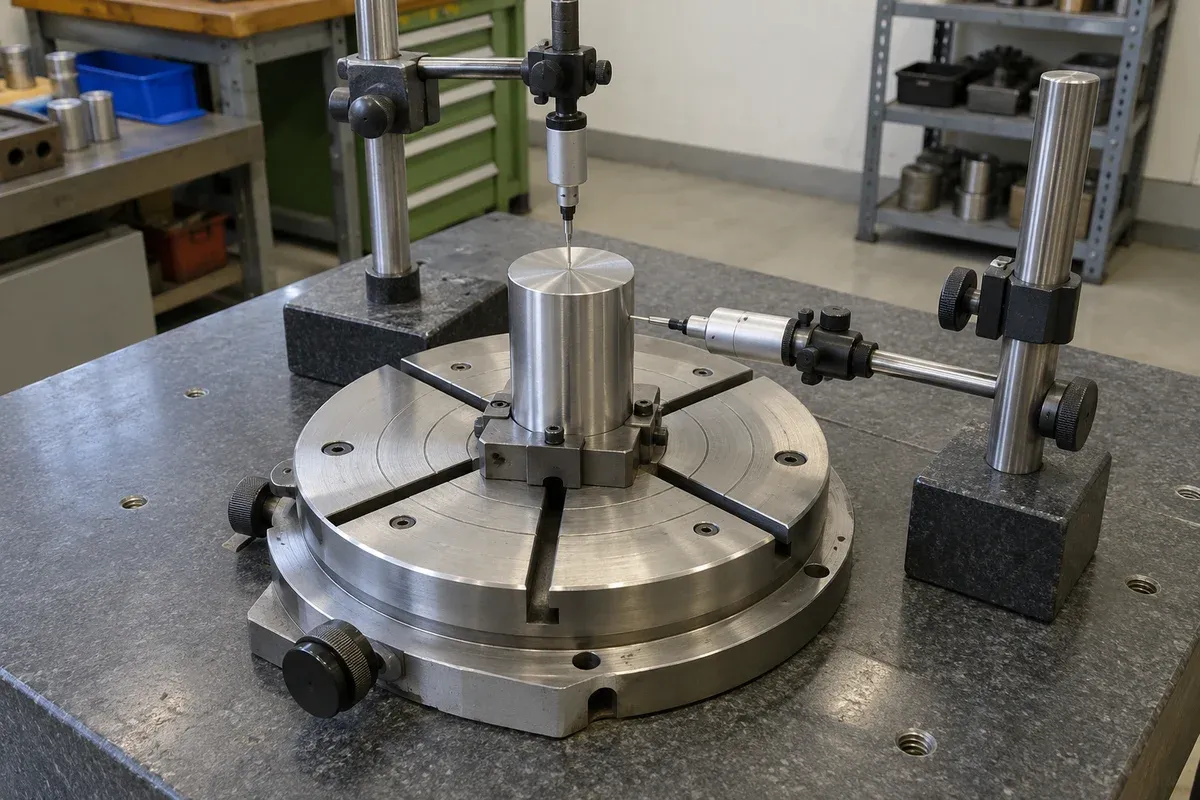
A rotary stage may need to place a part at a commanded angle, hold a rotation axis stable, or do both. The acceptance plan should state each objective independently. An angular placement result cannot stand in for a radial displacement result, and a smooth indicator trace does not prove accurate commanded angles.
Zaber’s rotary-stage selection guide distinguishes positioning performance from radial, axial and tilt error motion. It also cautions against equating a surface runout measurement with axis error motion. These distinctions provide the starting point for a test plan, not performance evidence for a different product.
Plan the angular positioning measurement
Choose an angular reference suitable for the required range and uncertainty. Document its coupling, alignment and relationship to the functional point. State target angles, approach directions, repetitions, speed and dwell. If the system operates over only a limited angular range, label the scope explicitly rather than implying complete-revolution verification.
Preserve commanded angle and externally observed angle as separate channels. Record the coordinate origin, angle wrapping convention and compensation state. A transition from 359 degrees to 0 degrees should be interpreted deliberately in the analysis, not allowed to create a spurious large error through arithmetic.
Keep repeated-return behavior separate from absolute angular placement. Similarly, a controller’s angular command increment is not proof of a corresponding physical move. The specification guide explains the general distinction between resolution, repeatability and accuracy; apply it consistently when the units are angular rather than linear.
Plan the displacement and tilt measurements
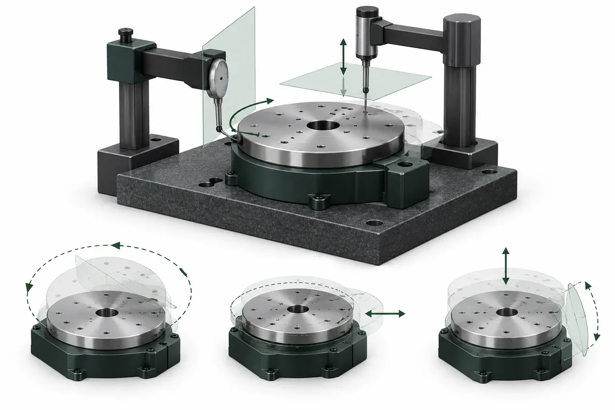
For radial and axial objectives, identify the reference artifact, sensing directions, axial height and radial measurement location. Record mounting eccentricity and artifact form as potential contributions. If the purpose is installed-part runout, those effects may be part of the application result. If the purpose is isolating axis error motion, the method must address their separation.
A tilt measurement needs an arrangement that observes angular change rather than merely a single displacement at an unspecified radius. Document any geometric conversion and its assumptions. Avoid turning a linear indicator reading into an angular specification without a known lever arm and an appropriate model.
Choose the number of rotations, rotation directions and sampling scheme according to the intended conclusion and applicable method. Retain angle-synchronized data where practical. A single revolution may not reveal all behavior relevant to repeated production cycles. Do not claim compliance with a metrology standard merely because the experiment resembles one of its diagrams.
Hypothetical example: indexing an optical component
Imagine a fixture that indexes an optical component to several angles while a nearby sensor requires the component center to remain stable. The proposed acceptance packet contains an angular placement test and separate radial and axial observations at the installed component. No stage rating, measured result or acceptance threshold is assumed.
If an indicator trace changes after the component is remounted, the team compares mounting and artifact contributions before assigning the change to the rotary bearings. Conversely, an unchanged radial trace does not establish that the angular index points are correct. Each result answers its own requirement, and the report preserves that separation.
Practical checklist for rotary verification
- Write distinct requirements for angular placement and axis error motion.
- Identify the angular reference and coordinate-wrapping convention.
- Record artifact identity, mounting method, radius and sensing height.
- State whether the result concerns installed-part runout or isolated axis behavior.
- Preserve direction, revolution number and angle-synchronized observations.
- Document the model used for any displacement-to-angle conversion.
- Attach uncertainty to each reported quantity in its own units.
Use NIST’s reporting guidance to make the uncertainty basis explicit. The completed packet should allow a reader to identify which physical quantity was measured without inferring it from the word “runout.” That clarity is more valuable than combining unlike results into a single rotary precision score.
Questions
Can a dial indicator on the stage rim establish angular accuracy?
No. That displacement trace does not directly measure commanded angular placement against an angular reference.
Is radial error motion the same as surface runout?
Not necessarily. Surface readings can include form and mounting contributions that must be separated for an axis-error claim.
Why specify the measurement height?
A reading at one axial location may have a different contribution from tilt than a reading at another height.
Sources & scope
Sources support the specific points described below. General engineering guidance and third-party examples do not establish a catalogue model's performance or suitability.
- Zaber: Selecting a Motorized Rotary Stage
Rotary positioning differs from radial, axial and tilt error motion; surface runout is not automatically radial error motion.
Accessed - NIST TN 1297: Reporting Uncertainty
Report uncertainty with its expression and basis.
Accessed
Related engineering resources
Continue reading
Accuracy & Metrology
Accuracy, repeatability and resolution: three separate acceptance questions
Turn accuracy, repeatability and resolution into separate acceptance requirements, with a worksheet for evidence, conditions and decisions.
Verification guide · 4 min read ·Accuracy & Metrology
Assessing velocity stability and following error during a scan
Plan scan-motion measurements with explicit trajectory definitions, acquisition bandwidth, payload and processing for velocity and following error.
Verification guide · 4 min read ·From requirements to a quotation
Review your stage requirements
Share the motion envelope, payload, orientation and acceptance criteria. Request confirmation of the exact configuration before ordering.
Request a Quote