Key takeaways
- Payload means the complete carried assembly, not only the workpiece.
- Give offsets in a defined coordinate frame and inertia about a named axis.
- Keep static loading and motion-profile requirements distinct.
Build the mass list from the moving boundary
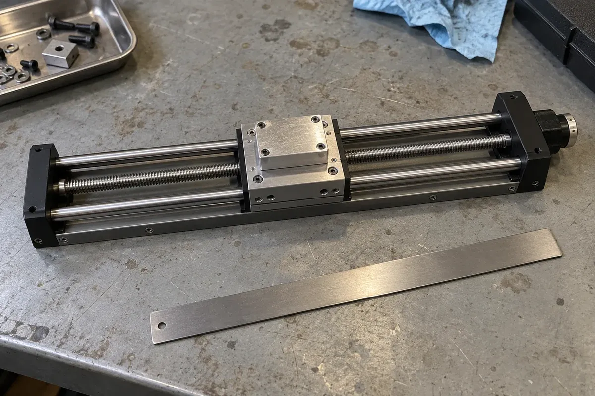
Start at the axis under review and identify everything it carries. Include the workpiece, clamps, adapter plates, upper axes, moving motor components where applicable, and attached services that contribute to the load. The useful boundary is physical, not administrative: a component supplied by another team still belongs in the moving assembly.
Record each item’s mass, source and revision. Distinguish measured values from CAD estimates and supplier data. If a component is not yet selected, keep its provisional allocation visible. This makes the total easier to update than an isolated number labeled payload.
Locate the center of mass in a defined frame
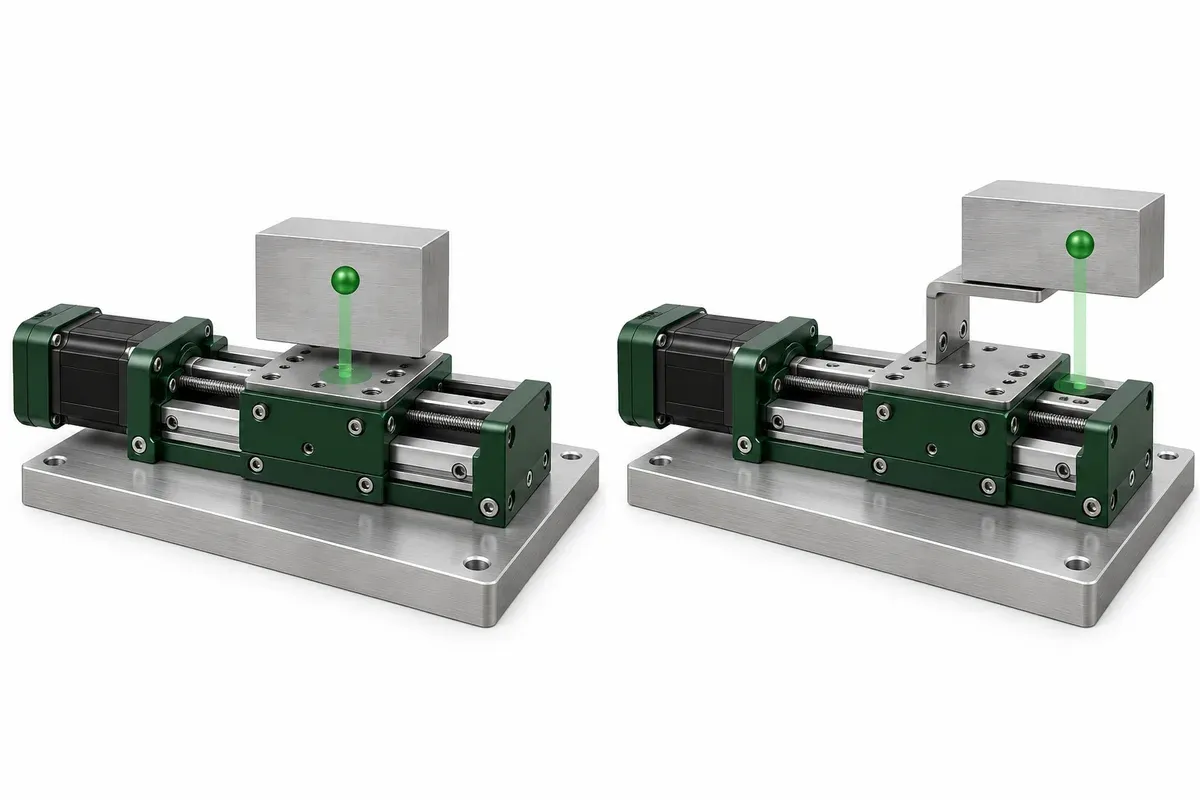
Draw the coordinate origin and axis directions on the mounting interface. Report the center-of-mass coordinates relative to that frame, with units. A statement that the load is “slightly off center” is difficult to review because it omits both distance and direction.
As a hypothetical example, an adapter carries a 2 kg assembly whose center of mass lies 80 mm from a relevant support reference in a direction perpendicular to gravity. Using 9.81 m/s², the gravity force is approximately 19.6 N and its moment about that reference is approximately 1.57 N·m. These are simplified static calculations, not allowable values or a finding that a stage is suitable.
The actual review may involve several force components and positions. Show how the center of mass moves when an upper axis or rotary fixture changes position. Do not substitute the centered position for a configuration that operates elsewhere.
Add orientation and external forces
State which direction gravity acts in the drawing. Identify whether a rotary axis is vertical, horizontal or otherwise inclined. Zaber’s rotary-selection guide explains that orientation changes the axial, radial and moment loads that need consideration. Use those categories to organize the input sheet, not to transfer that manufacturer’s ratings to another product.
List external forces from process contact, cables, hoses or other mechanisms. For each known force, identify its application point, direction and variation through the motion. If it is unknown, name the source and request a way to characterize it. An unexplained extra mass entry cannot describe a force that changes direction as a cable bends.
Report inertia with its axis and assumptions
For rotary motion, mass distribution matters as well as total mass. A compact assembly and an extended assembly can have the same mass while presenting different rotational inertia. Supply the inertia about the actual proposed rotation axis and state the units.
If using a CAD mass-properties report, verify the included parts, material assumptions and coordinate frame. Exclude neither adapters nor a carried fixture by accident. Provide the report with the assembly revision so it can be reproduced. A number copied without its axis can be unusable even if the calculation itself was correct.
Avoid inventing a motor sizing conclusion from inertia alone. Ask the supplier to review it together with the movement requirements and complete drive arrangement.
Describe the sequence that creates the dynamic task
Provide typical and limiting move distances or angles, the required cycle sequence and the available time for movement and settling. Explain whether the assembly moves continuously, indexes between stops or makes occasional setup adjustments. Identify any conditions that change between recipes.
Do not reduce the requirement to a maximum speed if the actual task depends on repeated short moves. Likewise, do not supply an acceleration number merely because another machine used it. Give the process objective and request confirmation of a suitable, documented motion profile for the proposed system.
Send a traceable supplier input sheet
A complete sheet should contain:
- Assembly drawing revision and moving-component list.
- Mass values with measured or estimated status.
- Coordinate origin, axis directions and gravity direction.
- Center-of-mass location at relevant configurations.
- External forces with application points and uncertainty.
- Rotary inertia with reference axis and calculation assumptions.
- Operating sequence and required process timing.
Ask the supplier to identify assumptions used in its recommendation and any missing evidence. Save the sheet with the quotation. When a fixture gains a longer bracket or a new carried component, revise the mass properties and geometry before relying on the previous selection. The point is not to provide more numbers; it is to provide numbers whose meaning survives the handoff between designers.
Questions
Why is total mass insufficient for a rotary-stage review?
Mass does not describe its distribution about the rotation axis. Geometry, center-of-mass offset and rotational inertia can change the required review even when mass is unchanged.
Can CAD supply the inertia value?
CAD can provide a useful value if materials, included components and the reference axis are correct. State those assumptions and have the result reviewed.
Should I report cable forces as extra kilograms?
Describe the actual force direction, application point and variation where known. Do not hide a directional external force inside an unexplained mass allowance.
Sources & scope
Sources support the specific points described below. General engineering guidance and third-party examples do not establish a catalogue model's performance or suitability.
- Zaber rotary-stage selection guide
Supports the distinction among orientation-dependent axial, radial and moment loading and the role of payload rotational inertia. The input sheet and static example are original.
Accessed
Related engineering resources
Continue reading
Stage Selection & Buying Guides
Compare quotations by included components, options and responsibilities
Compare stage quotations by separating included hardware, optional components, customer responsibilities and the evidence needed for acceptance.
Selection guide · 4 min read ·
Stage Selection & Buying Guides
Choosing a vertical lift instead of mounting a linear stage vertically
Compare a dedicated vertical lift with a vertically mounted linear stage by checking layout, gravity loading, support and configuration-specific evidence.
Selection guide · 4 min read ·From requirements to a quotation
Review your stage requirements
Share the motion envelope, payload, orientation and acceptance criteria. Request confirmation of the exact configuration before ordering.
Request a Quote