Key takeaways
- Identify the reference used for the specified rotation-center height.
- Include the holder and adapter in the part-location calculation.
- Nominal pivot placement does not prove zero translation or optical stability.
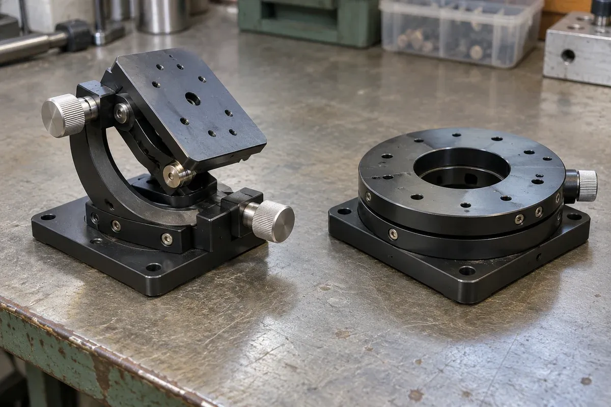
A goniometer is useful when an angular adjustment should occur about a point above its platform. To benefit from that geometry, the fixture must place the relevant part feature at the intended pivot. Selecting a center-height value from a catalogue is only the beginning: the drawing reference, adapter thickness and holder geometry determine where the feature actually sits.
Identify the pivot and its dimensional reference
Find the rotation axis in the verified drawing and determine how its position is dimensioned. Record the reference surface, the platform configuration and the direction of the axis. Do not substitute overall stage height for rotation-center height or assume all suppliers use the same reference convention.
Newport’s goniometer description illustrates rotation about a transverse axis above a platform and model-specific shared-center arrangements. That establishes the general geometric concept, not dimensions, compatibility or performance for the goniometers listed on this site.
Build the holder height from the functional point
Choose the point on the workpiece that matters to the task. For an optical experiment it could be an illuminated surface feature; for another process it may be a contact or alignment reference. State it explicitly rather than using the center of the part as an undefined shorthand.
Trace the distance from the goniometer reference through the adapter, holder and workpiece to that point. Include recesses and stepped surfaces with their correct signs. A holder that places the part’s outside envelope at the right height can still place its functional feature elsewhere.
If workpieces vary, identify which dimensions vary and how their feature location will be controlled or measured. The nominal fixture drawing should not hide a family of different pivot offsets behind one representative component.
Consider angular motion and neighboring geometry
Place the complete holder in the angular envelope, including fasteners and services. Even when the chosen feature lies near the nominal rotation center, the rest of the part moves around it. Check access for illumination, detectors, probes or assembly tools over the required angular range.
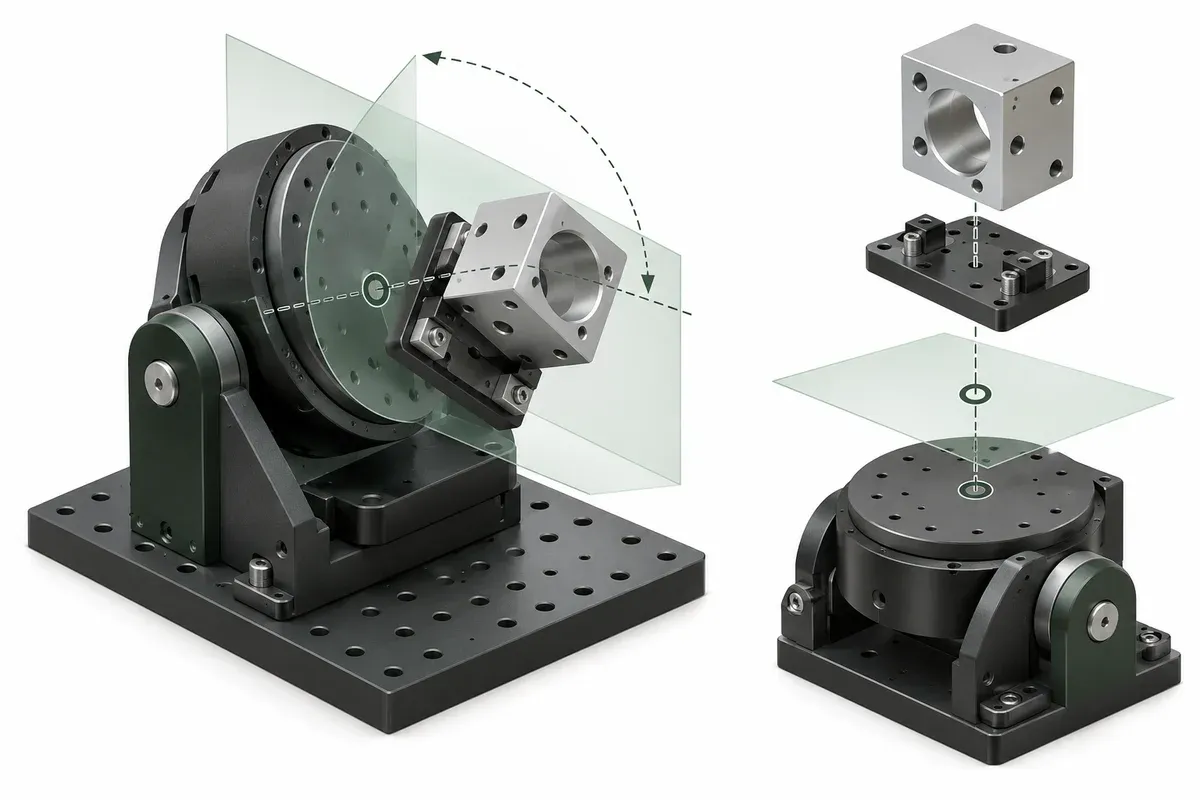
For stacked angular axes, review the location and direction of each rotation axis in the assembled configuration. Adding an adapter between nominally compatible components can change their relationship. Ask for the relevant configuration drawing rather than assuming that two center-height numbers prove the axes intersect.
Keep ideal geometry separate from verification. The actual motion of the functional feature can reflect stage behavior, mounting alignment and fixture placement. Define what needs to be measured in the complete setup without promising that a nominal center placement produces zero translation.
Pivot-location checklist
- Mark the intended functional point on the workpiece drawing.
- Identify the documented rotation axis and its dimensional reference.
- Include adapters, recesses and holder dimensions in the height chain.
- Record workpiece variants that change feature location.
- Review the complete swept holder and service envelope.
- Check relationships between angular axes in stacked arrangements.
- Define the assembled measurement needed to assess the task.
- Leave unverified geometry and performance claims out of the release.
A useful enquiry includes a sectioned view through the proposed pivot and a second view showing the axis direction. Together they reduce ambiguity about a feature that can be difficult to describe with a single photograph.
Record the reference configuration used for the holder drawing. If the platform is drawn at a nonzero angular setting, the relationship between its mounting face and the intended pivot can be harder to interpret. A clearly labelled section avoids using a tilted view as though it represented the neutral geometry.
Hypothetical example: tilting a coated sample
Suppose a fixture is intended to vary the angle of a coated sample about a point on its upper surface. The designer initially aligns the middle of the sample thickness with the nominal pivot. Reviewing the functional point reveals that the surface of interest lies elsewhere.
The team revises the height chain and checks the holder’s angular clearance. It then plans a measurement of the actual feature motion in the assembled fixture. This hypothetical example supplies no center-height value or allowable drift. It shows why the task’s point of interest must govern the geometric construction.
Browse goniometer stages to identify candidate geometries, then obtain the exact-model drawing before finalizing the holder.
Questions
Is rotation-center height always measured from the top platform?
Do not assume the reference. Check the exact drawing and definition for the selected model.
Can two arbitrary goniometers share a pivot when stacked?
No. Their geometry, orientation and intervening interfaces must be reviewed; shared-center arrangements are configuration-specific.
Will a point at the nominal center remain perfectly stationary?
A nominal geometric construction is not a measured performance guarantee. Assembly and stage errors still require evaluation.
Sources & scope
Sources support the specific points described below. General engineering guidance and third-party examples do not establish a catalogue model's performance or suitability.
- Newport BGS80CC goniometer information
General goniometric rotation and reference geometry; not a compatibility or accuracy claim for our goniometers.
Accessed
Related engineering resources
Continue reading
Mounting & Mechanical Integration
Checking the support surface before installing a precision stage
Organize a support-surface readiness review around documented requirements, contact geometry, surface condition and traceable inspection evidence.
Integration guide · 4 min read ·
Mounting & Mechanical Integration
Choosing the order of an XYZ stack
Compare XYZ stack arrangements through moving mass, payload offsets, working height and access before selecting a mechanical layout.
Integration guide · 4 min read ·From requirements to a quotation
Review your stage requirements
Share the motion envelope, payload, orientation and acceptance criteria. Request confirmation of the exact configuration before ordering.
Request a Quote