Key takeaways
- Mass alone does not describe an offset payload.
- Include holders, adapters and carried services in the mass model.
- Request allowable loading for the actual orientation and motion.
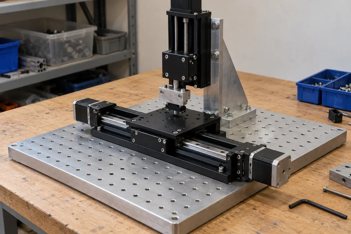
A stage may carry a small part on a tall holder, a heavy fixture close to the platform, or an assembly whose mass distribution changes during use. These arrangements cannot be described adequately by the workpiece mass alone. Preparing a useful load enquiry means describing where all the carried mass is and how that geometry changes.
Define the complete carried group
Start with a bill of moving components. Include the workpiece, holder, adapters, brackets, attached instruments and the relevant portions of services. In a stacked arrangement, upper stages belong in the carried group of lower axes. A component that is stationary relative to one axis can still move with another.
Give each mass a source: drawing, weighing record, supplier information or provisional estimate. Mark estimates clearly. The purpose is not to create a falsely precise center-of-mass value from uncertain inputs, but to reveal which unknowns could change the selection. Updating a heavy holder late in the design should trigger a loading review.
Show offsets in a named coordinate system
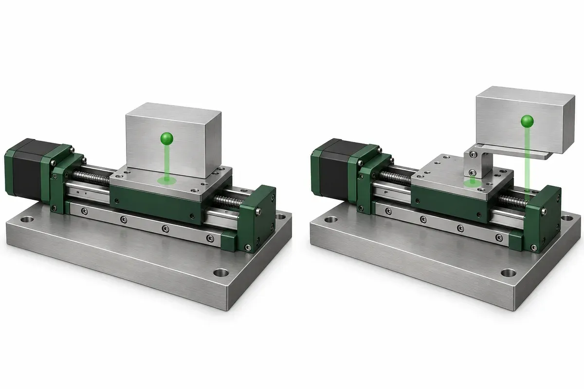
Locate the combined center of mass relative to an identified stage reference and state the axis orientation. A three-dimensional sketch is often clearer than a sentence such as load mounted centrally. Include the positions where an upper axis moves the carried group farther from the lower support.
Keep mass-center location distinct from the process point. A probe tip may be far from the center of mass; both locations matter, but for different questions. The rotary-stage selection reference discusses loading as more than a single mass figure. Its product ratings are not transferable to the stages in this catalogue.
Compare layout changes before assuming capacity
Moving an instrument closer to its supporting structure may reduce a load offset, but it can obstruct access or alter the working geometry. Compare alternative holder designs with those tradeoffs visible. Do not present shorter or lower as automatically sufficient for approval.
Describe intended motion, including which axes move simultaneously and whether the mass distribution changes. Static positioning and repeated acceleration are different review cases. A reviewer may need information about the motion profile, external process forces and services before assessing the complete arrangement. Avoid supplying an invented acceleration limit to fill that gap.
Payload-location checklist
- List every component carried by each axis.
- Identify measured, documented and estimated masses separately.
- Locate the combined mass center in the assembly coordinate frame.
- Show how that location changes over the intended travel.
- Mark the functional process point independently.
- Include foreseeable changes in tooling or workpiece variant.
- Describe external forces and the intended motion sequence.
- Request a configuration-specific loading assessment.
Keep a version of this information with the fixture drawing. A quoted loading assessment for one holder should not silently become approval for a later holder that is taller, heavier or mounted farther out. The change record should show which input has changed and who decides whether reassessment is necessary.
Specify the payload configuration used for each operating case. A loaded gripper and an empty gripper may have different mass distributions, while a removable sample tray may contain different arrangements of parts. Recording those cases prevents a single nominal center from being mistaken for a complete description of the application. The reviewer can then identify which case governs each aspect of the assessment.
Hypothetical example: a lightweight sensor on a tall mast
Suppose a sensor itself is light, but its holder raises it well above a translation platform. The team initially sends only the sensor mass in a quotation enquiry. A revised component list adds the mast, clamp and adapter, and an assembly sketch identifies their combined position.
An alternative holder brings the sensor nearer the support but blocks the cable connector. The designer therefore compares both the mechanical loading inputs and service access before asking for review. This fictional example contains no allowable moment or safe operating mass. Its lesson is that a complete load description enables a meaningful response.
The linear-stage catalogue provides model-level information for shortlisting. Submit the proposed payload arrangement alongside the selected model so its listed loading data can be interpreted in the correct context, with unresolved conditions explicitly identified.
Questions
Is a payload below the listed mass rating automatically suitable?
No. The rating basis, orientation, offsets, dynamic conditions and complete assembly must also be considered.
Does centering the workpiece center the payload?
Not necessarily. Holders, tooling and adapters contribute to the combined center of mass.
Can this guide supply an allowable moment?
No. Obtain configuration-specific limits and engineering review from the relevant product documentation and supplier.
Sources & scope
Sources support the specific points described below. General engineering guidance and third-party examples do not establish a catalogue model's performance or suitability.
- Zaber rotary-stage selection guide
General distinction between rotary geometry, loading and application requirements; not evidence of our product ratings.
Accessed
Related engineering resources
Continue reading
Mounting & Mechanical Integration
Checking the support surface before installing a precision stage
Organize a support-surface readiness review around documented requirements, contact geometry, surface condition and traceable inspection evidence.
Integration guide · 4 min read ·Mounting & Mechanical Integration
Choosing the order of an XYZ stack
Compare XYZ stack arrangements through moving mass, payload offsets, working height and access before selecting a mechanical layout.
Integration guide · 4 min read ·From requirements to a quotation
Review your stage requirements
Share the motion envelope, payload, orientation and acceptance criteria. Request confirmation of the exact configuration before ordering.
Request a Quote