Key takeaways
- An adapter creates two interfaces that each need review.
- Assign plate mass and payload offsets per axis; a fixed base plate is not moving load for its own axis.
- Keep locating, fastening and service-access requirements separate.
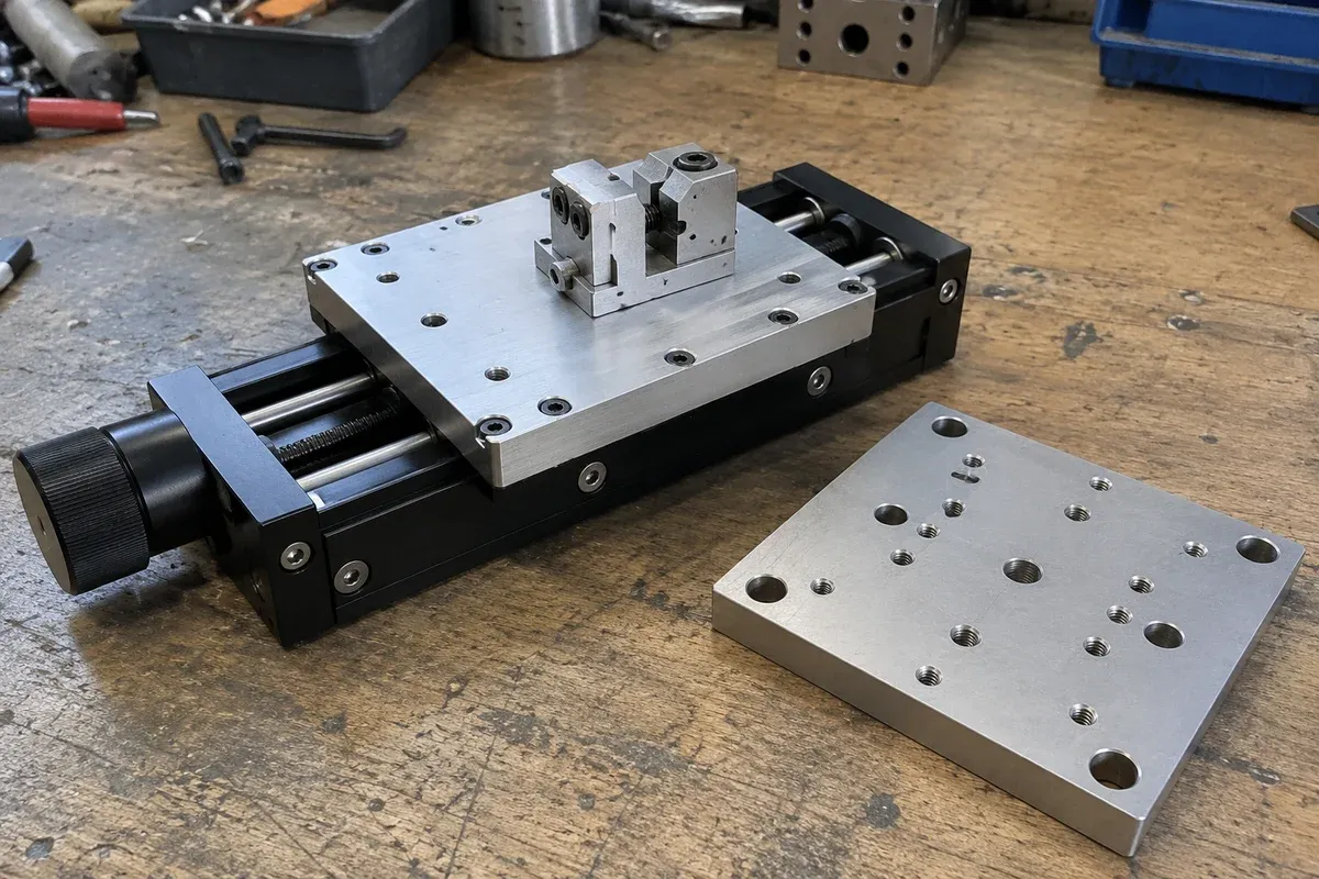
Plan an adapter plate by documenting the stage-side and fixture/support-side interfaces separately, then reviewing their combined geometry, access and mechanical effects before releasing a drawing. The plate changes the mechanical stack and adds another set of joints. A useful concept review therefore considers geometry, support, access and the consequences of adding another component, beyond whether two groups of holes fit within one rectangle.
Define both mating interfaces independently
Start with a verified drawing for the stage and one for the fixture or supporting structure. Mark which surface of the adapter contacts each part. Record pattern coordinates, thread systems, fastener entry direction and any locating features separately for the upper and lower faces.
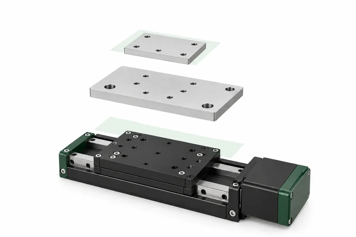
Use this two-face register with the concept drawing. Record the actual source for each entry; leave an unknown marked as awaiting confirmation rather than completing it from the illustration.
| Interface record | Stage-side face | Fixture/support-side face |
|---|---|---|
| Mating drawing and revision | Exact stage, attachment surface (base or carriage), drawing revision and source | Exact fixture or support drawing, revision and source |
| Origin, orientation and viewed face | Datum, coordinate directions and face viewed; identify any mirrored view | Datum, coordinate directions and face viewed; define its rotation and offset relative to the stage-side reference |
| Original units and thread system | Original nominal units and complete thread designation from the drawing | Original nominal units and complete thread designation from the drawing |
| Function of each hole or feature | Identify clearance, tapped and locating features separately | Identify clearance, tapped and locating features separately |
| Fastener entry and head envelope | Entry side, specified hardware and space occupied by its head or recess | Entry side, specified hardware and space occupied by its head or recess |
| Tool and removal access | Tool approach and access before and after the mating part is fitted | Tool approach and access with adjacent parts present; identify parts removed first |
| Support, height and load path | Contact regions and load path across the named stage-base or carriage interface | Contact regions and load path at the fixture or support; resulting installation height or payload offset, as applicable |
Do not combine metric and inch dimensions into a convenient rounded pattern. An apparently small discrepancy can be an actual incompatibility. Keep nominal values in their original units in the interface register and use controlled conversions only where the drawing requires them. Establish whether holes provide clamping clearance, thread engagement or location; one feature should not silently be assigned all three roles.
The Zaber mounting guide distinguishes direct mounting from named adapters or brackets for specific upper/lower stage pairs, with configuration notes. Request equally specific evidence for the proposed pair; this reference establishes no compatibility for this catalogue.
Check where the two patterns interact
Overlay the patterns at the intended orientation. Review more than hole centers: include head envelopes, counterbores, pockets, locating features and the space remaining between features. A lower attachment hidden beneath an upper component needs a planned installation and removal route. A hole-pattern overlay is a planning aid. It does not replace review of locating features, stiffness or joint design, even when every hole center clears.
The mechanical reviewer should determine whether the remaining material and contact regions are appropriate. Do not choose plate thickness from appearance or a rule copied from a different assembly. Material selection, stiffness, joint design and expected loading belong together in that review. If important details remain unknown, retain a concept drawing rather than issuing a manufacturing drawing with guessed values.
Include the height and load-path changes
Identify whether the adapter attaches to the stage carriage or the stage base. A plate mounted on a moving carriage moves with that axis and can raise or shift the payload relative to the carriage. The new concept illustration shows this carriage-to-fixture case only.
A plate between the stage base and a fixed supporting structure is stationary for that axis. It changes the overall installation height, but does not necessarily change the payload’s offset relative to the carriage. Record the relevant height or offset in the complete assembly layout, including camera focus, optical axis height or probe reach where applicable. A plate that solves the attachment problem can create an access or alignment problem elsewhere.
In a stacked system, a plate stationary relative to an upper stage can still be carried by a lower axis. Assign the plate’s mass and its offset to each axis that actually carries it, and trace the load path separately for each moving axis throughout its travel. The stage catalogue is useful for shortlisting, but it does not approve a custom plate, the new joint or a particular offset load. Submit the complete proposed arrangement when requesting configuration review.
Record design checks before drawing release
Use the register and the following review record together. Each open item needs an owner and a recorded resolution; an unchecked row is not evidence that the interface is acceptable.
| Review check | Observable evidence to attach | If unresolved |
|---|---|---|
| Pattern and recess conflicts | Revision-linked overlay plus sections showing heads, counterbores, pockets and remaining material | Mark each collision; revise the concept and recheck both faces |
| Location, support and joint behavior | Mechanical review of the actual locating scheme, contact regions, material, stiffness and expected loading | Identify missing inputs and keep drawing release pending the review |
| Assembly and removal sequence | Ordered assembly sketch showing fastener entry, tool paths and the parts removed for access | Revise the sequence or layout; record any access still unproven |
| Height, moving envelope and load path by axis | Assembly layout through the intended travel, identifying stationary/moving parts and plate mass and offsets for each carrying axis | Return changed offsets and clearances to the configuration review |
| Inspection access | Inspection plan stating which interface features are checked before assembly and how the plate revision is recorded | Agree a checkable method before features become concealed |
| Supplier interface questions | Written confirmation tied to the exact component and drawing revision | Keep the question open with its owner; do not infer approval from catalogue similarity |
| Drawing release and later changes | Review record identifying the released revision, reviewer and resolved items | Retain concept status; a changed mating drawing requires both interfaces to be reviewed again |
Keep this record with the concept and its drawing revisions rather than in a disconnected email. Manufacturing and assembly teams should agree when interface geometry can be inspected and how that record identifies the actual plate revision.
Hypothetical example: converting a sensor fixture
Imagine a sensor fixture to be mounted on a moving stage carriage, with its attachment pattern rotated relative to the carriage pattern. The first adapter concept simply combines both patterns. In the review, one upper threaded feature intersects a lower counterbore, and the sensor body blocks access to another fastener.
The team compares a larger plate, a different fixture orientation and a removable upper fixture. The larger option also increases the moving footprint, so it must return to the clearance review. No option is declared acceptable solely because its holes no longer overlap. The example is hypothetical and provides no approved plate thickness, engagement length or load rating.
For a proposed multi-axis arrangement, describe exactly where each adapter sits. A supplier can review the intended stack more effectively when the package includes both interface drawings and the full assembly, identifying the parts carried by each axis, rather than a plate outline alone.
Questions
Can an adapter solve any hole-pattern mismatch?
No. Available material, hardware access, support footprint and loading may make a particular conversion unsuitable.
How thick should the plate be?
Thickness must follow structural and interface review for the actual geometry and loading; there is no universal value.
Should both sides use the same datum?
The drawing should define their relationship to a common reference scheme, while distinguishing each mating interface.
Does every adapter plate add moving mass to every axis?
No. Count a plate as moving load only for an axis that carries it. In a stack, a plate can be stationary for an upper stage yet carried by a lower axis.
Sources & scope
Sources support the specific points described below. General engineering guidance and third-party examples do not establish a catalogue model's performance or suitability.
- Zaber: Multi-Axis Mounting Guide
Model-specific mounting combinations and configuration limitations; no approval of this catalogue.
Accessed
Related engineering resources
Continue reading
Mounting & Mechanical Integration
Checking the support surface before installing a precision stage
Organize a support-surface readiness review around documented requirements, contact geometry, surface condition and traceable inspection evidence.
Integration guide · 4 min read ·
Mounting & Mechanical Integration
Choosing the order of an XYZ stack
Compare XYZ stack arrangements through moving mass, payload offsets, working height and access before selecting a mechanical layout.
Integration guide · 4 min read ·From requirements to a quotation
Review your stage requirements
Share the motion envelope, payload, orientation and acceptance criteria. Request confirmation of the exact configuration before ordering.
Request a Quote