Key takeaways
- Route services by moving group rather than by appearance.
- Use actual cable and hose requirements for repeated motion.
- Include service forces and connector access in the mechanical review.
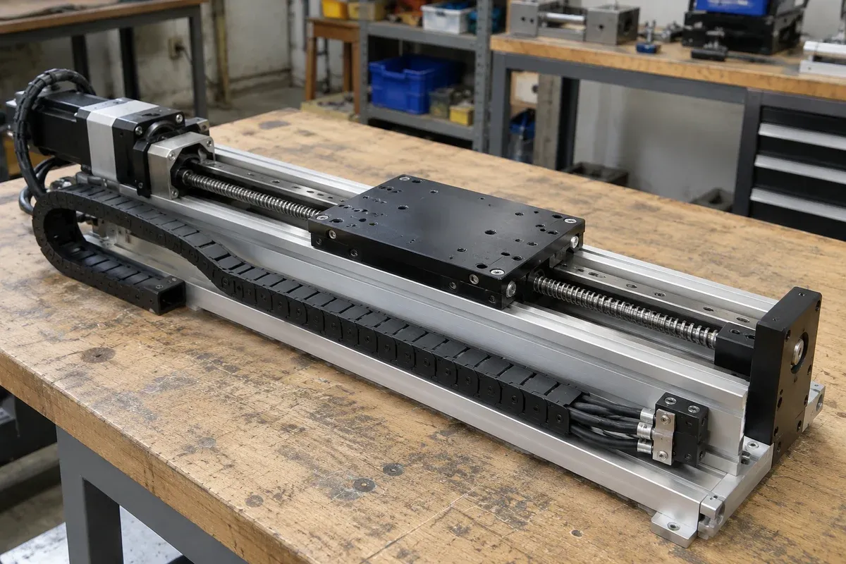
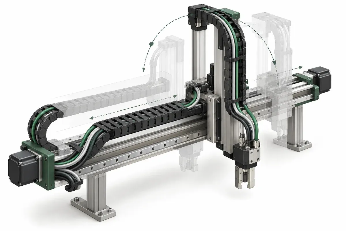
Cables and hoses connect the moving fixture to the rest of the machine, so their routing belongs in the mechanical design. A service loop that looks tidy at the center position can become a source of interference, unwanted loading or difficult maintenance elsewhere. Start the routing plan alongside the axis layout, before every convenient attachment point has been occupied.
Divide the machine into moving groups
Identify the fixed frame and each group of components that moves together. Then draw every service transition between groups. A cable to a camera on a Z axis above XY may pass through several different motion relationships; treating it as one loose loop hides those relationships.
For each service, record its endpoints, connector orientation and required function. Separate electrical cables, optical fibers, pneumatic hoses and other lines where their requirements differ. Do not assume one routing method suits all services simply because their outside diameters are similar.
Gather component-specific motion requirements
Obtain guidance for the exact cable or hose, including the intended type of motion. Repeated bending, torsion and a static bend are different uses. Record applicable bend requirements, environmental restrictions and any manufacturer conditions for strain relief or separation.
igus cable-carrier guidance supports using the cable or hose manufacturer’s bending recommendations and reviewing separation and strain relief. Its detailed values are not universal stage-integration limits. This article therefore does not prescribe a common radius, spacing percentage or cable-life claim.
Where documentation is missing, mark the routing provisional. A cable supplied with an instrument may be suitable for connection without being documented for the intended repeated movement. That uncertainty should reach the instrument owner before the fixture layout is released.
Review the force path and occupied space
Show where service reactions enter the moving assembly. A connector should not silently become the structural anchor for a moving cable bundle. Identify attachment concepts for qualified review and consider how the route behaves across the full motion envelope.
Account for the flexible loop’s occupied space, not just its nominal centerline. Include nearby brackets, sharp edges, moving parts and the possibility of a changed workpiece. For hoses, note operating conditions that can affect their behavior and obtain the relevant supplier guidance rather than assuming an unpressurized layout represents every state.
Also reserve connector mating and removal space. A replaceable instrument is not practically replaceable if its connector can only be reached by dismantling the entire axis stack. Distinguish routine service access from maintenance that requires controlled procedures.
Routing-plan checklist
- Identify each service and its fixed and moving endpoints.
- Map transitions between motion groups separately.
- Collect the exact component’s dynamic-use requirements.
- Reserve bending and connector-access envelopes.
- Identify proposed anchors and force-transfer locations.
- Check interaction with all adjacent moving components.
- Record replacement access and service identification labels.
- Assign unresolved routing conditions to an engineering owner.
Keep this record linked to the cable part numbers. Substituting a visually similar cable can change the routing assumptions, so replacement equivalence should include motion-related requirements, not only connector compatibility.
Make room in the drawing package for a routing view rather than hiding services in a general assembly view. Label proposed anchors and transition points so reviewers can discuss the same locations. When a route remains provisional, show that status directly on the view and list the missing component information that prevents release.
Hypothetical example: adding air to an XY fixture
Consider an XY fixture originally designed with a single electrical cable. A later version adds a pneumatic line to a gripper. The designer initially ties the hose into the existing loop. Review finds that its routing requirements and connection direction differ, and that the new bundle occupies space near the X-axis motor.
The team creates separate service records and revises the routing concept before evaluating the complete assembly. It also updates the moving-load description. This hypothetical example does not validate any hose, cable carrier or attachment method. It demonstrates why a small functional change can require a fresh mechanical routing review.
When enquiring about multi-axis stages, include the services carried by the payload. Their interfaces and proposed paths help define the real integration task more accurately than a stage-only drawing.
Questions
Can a static cable bend rating be used for repeated motion?
Do not assume so. Obtain the applicable dynamic-use guidance for the exact cable and motion type.
Does extra slack always help?
No. An uncontrolled loop can enter another motion envelope, rub nearby parts or impose changing forces.
Is a hollow stage automatically a rotary cable feedthrough?
No. An opening supplies geometric access, not unlimited cable rotation or an integrated rotary connection.
Sources & scope
Sources support the specific points described below. General engineering guidance and third-party examples do not establish a catalogue model's performance or suitability.
- igus cable-carrier filling and routing guidance
Supports using cable-specific bend guidance, separation and appropriate strain relief; no universal bend-radius value is prescribed.
Accessed
Related engineering resources
Continue reading
Mounting & Mechanical Integration
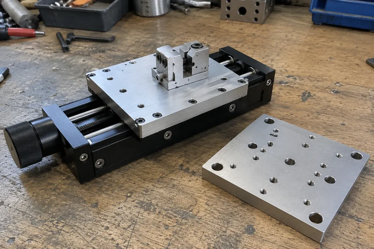
Checking the support surface before installing a precision stage
Organize a support-surface readiness review around documented requirements, contact geometry, surface condition and traceable inspection evidence.
Integration guide · 4 min read ·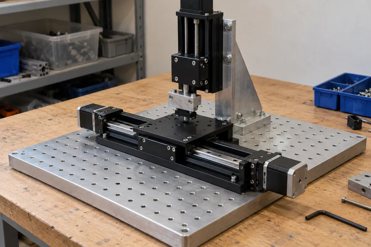
Mounting & Mechanical Integration
Choosing the order of an XYZ stack
Compare XYZ stack arrangements through moving mass, payload offsets, working height and access before selecting a mechanical layout.
Integration guide · 4 min read ·From requirements to a quotation
Review your stage requirements
Share the motion envelope, payload, orientation and acceptance criteria. Request confirmation of the exact configuration before ordering.
Request a Quote