Key takeaways
- Check the whole moving assembly, including connectors and tools.
- Intermediate and combined-axis positions can matter as much as endpoints.
- Geometric clearance review does not replace machine risk assessment.
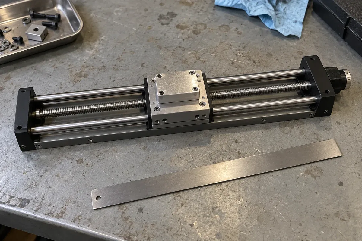
The travel printed on a stage page describes an axis, not the empty space required by a finished machine. A payload, connector or tool can extend beyond the stage footprint and sweep into nearby equipment. Clearance planning therefore starts with a complete moving assembly and a defined set of configurations, not a single attractive CAD view.
Separate stationary and moving objects
Create two inventories. The stationary list includes enclosure panels, support structures, optics, loading fixtures and fixed service entries. The moving list includes the stage platform, payload, workholding, fastener heads, connector backshells and anything carried by another axis.
Give each object an owner and a drawing or model revision. Simplified envelopes are useful during concept development, provided their assumptions are recorded. A box representing a connector must include its actual mating direction and cable exit allowance, rather than only the connector body. Replace provisional envelopes as verified information becomes available.
Review motion paths and combinations
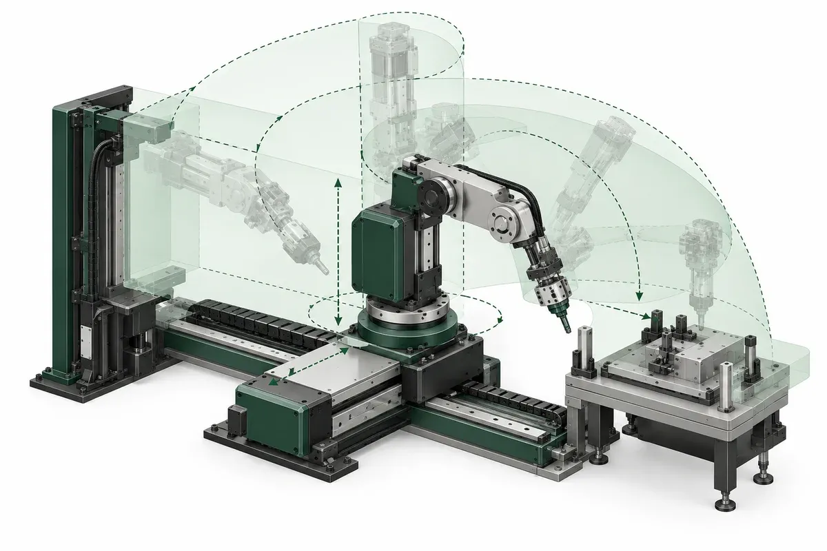
A single-axis translation is only the simplest case. In an XYZ stack, a part can occupy many combinations of X, Y and Z. In a rotary assembly, a corner may extend farthest from the center at an intermediate angle. In either case, checking a few screenshots does not automatically cover the complete swept space.
Distinguish process positions from loading, service and recovery configurations. A fixture may have ample clearance during inspection but insufficient space to insert a part. Define which motions and states belong in the review and which remain prohibited pending assessment. This is a design exercise for qualified reviewers, not a recommendation to test uncertain clearances by running hardware.
Treat flexible services as moving geometry
Cables and hoses do not occupy a rigid CAD shape throughout motion. Their loop, attachment points and bending requirements affect the envelope. Obtain requirements for the actual service components, including any difference between static installation and repeated flexing.
igus routing guidance emphasizes cable-specific bending and freedom of movement. Here, that supports reserving a reviewed service envelope. It does not provide a bend radius or routing approval for an unspecified cable on a positioning stage.
Include service access as well as motion. A connector can clear an enclosure when plugged in but lack space for disconnection. A tool can fit at the center position but become inaccessible at the configuration selected for maintenance.
Envelope-review checklist
- Identify every rigid object carried by each moving axis.
- Record the full set of intended axis combinations and paths.
- Include loading, tooling exchange and planned service configurations.
- Represent connector mating space and flexible-service envelopes.
- Review intermediate rotary positions and protruding payload corners.
- Account for dimensional uncertainty and changes to the workpiece family.
- Assign unresolved close approaches to a named mechanical reviewer.
- Keep geometric findings separate from the machine safety approval.
Document the basis for each required clearance rather than labelling every visible gap acceptable. Manufacturing tolerances, component movement and application risks must be considered in that decision. A collision-free idealized model alone is not evidence of a safe machine.
Give every close approach a reference on the assembly drawing. This lets a later reviewer find the exact location and understand which components define it. If an enclosure panel or connector changes, the affected close approaches can then be revisited without repeating an unstructured visual search of the entire model.
Hypothetical example: an offset camera connector
Imagine a camera on a Y stage moving over a sample held on an X stage. At the four corner positions, the camera body clears the enclosure. During a tooling change, however, its side connector must be withdrawn along a direction blocked by the enclosure wall.
The team also discovers that the cable loop passes close to an upper bracket at an intermediate Y position. It revises the service layout and records a new configuration for review. This fictional example shows two different envelopes: the working motion envelope and the access envelope. It does not prescribe a minimum gap or an operating workaround.
Use the stage selector to identify candidate motion ranges, then carry the selected geometry into a fixture-level envelope review. Selection and clearance verification are linked activities, but neither substitutes for the other.
Questions
Are the two end positions enough for a clearance review?
Not necessarily. Rotation, linked motion and flexible services can create a larger envelope at intermediate positions.
Do software limits establish safe physical clearance?
They may form part of a reviewed control strategy, but they do not independently validate the mechanical envelope or machine safety.
What clearance value should I use?
Set it through the application review, accounting for tolerances, motion, services and risks. No universal gap is appropriate.
Sources & scope
Sources support the specific points described below. General engineering guidance and third-party examples do not establish a catalogue model's performance or suitability.
- igus cable-carrier filling and routing guidance
Supports using cable-specific bend guidance, separation and appropriate strain relief; no universal bend-radius value is prescribed.
Accessed
Related engineering resources
Continue reading
Mounting & Mechanical Integration
Checking the support surface before installing a precision stage
Organize a support-surface readiness review around documented requirements, contact geometry, surface condition and traceable inspection evidence.
Integration guide · 4 min read ·
Mounting & Mechanical Integration
Choosing the order of an XYZ stack
Compare XYZ stack arrangements through moving mass, payload offsets, working height and access before selecting a mechanical layout.
Integration guide · 4 min read ·From requirements to a quotation
Review your stage requirements
Share the motion envelope, payload, orientation and acceptance criteria. Request confirmation of the exact configuration before ordering.
Request a Quote