Key takeaways
- State which angle is varied and relative to which optical reference.
- Place the sample feature at a verified pivot, not an assumed table center.
- Evaluate detector access and beam geometry across the intended angular range.
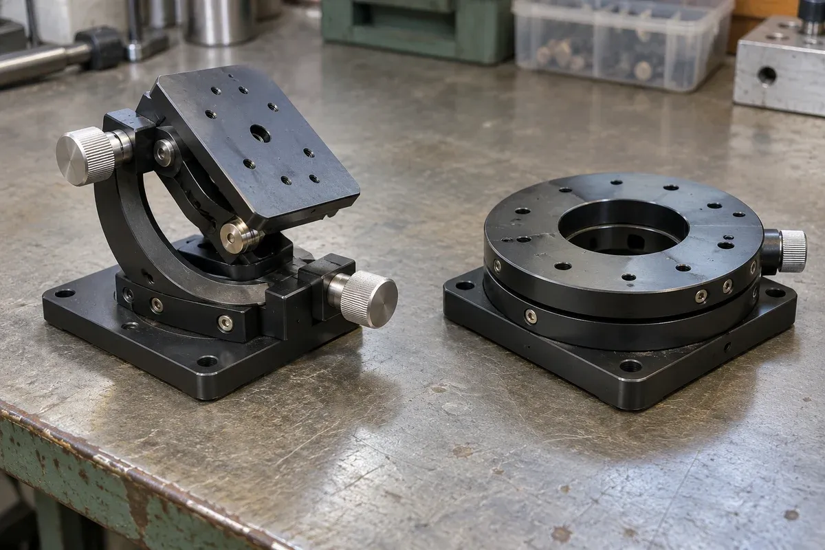
An angle-dependent optical experiment needs a precise definition of the angle being changed. Rotating a sample, rotating a detector and changing the incidence direction are different operations. A goniometer can be considered only after the experiment identifies which relationship matters and where its pivot must be located.
This guide develops a prospective fixture brief. It does not establish optical measurement accuracy, laser safety or suitability of catalogue stages for a particular experiment.
Define the independent angular variable
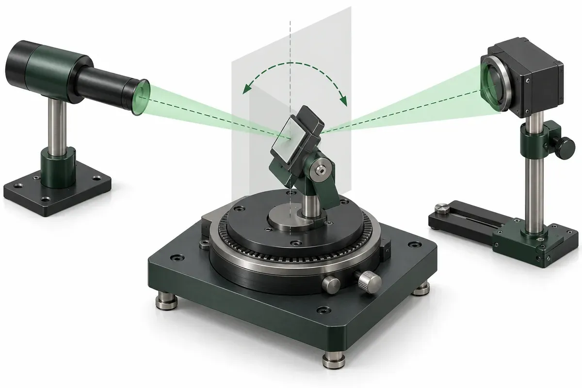
Draw the sample reference surface, incident direction and detector arrangement. Label the angle used in the experiment and state its zero convention. If more than one angle changes, assign each its own definition rather than reuse a generic “theta.”
Specify what should remain invariant while the angle changes. The intended measurement spot, source location or detector distance may be important. Identify which invariants are established by geometry and which require observation or correction.
Record how zero will be established. A stage reference position is a mechanical state; the experimental angular zero may require an optical or sample-based reference. The relationship between the two needs a verification method.
Reconcile the elevated pivot with the sample
Newport’s goniometer description illustrates rotation about an axis above the platform. The relevant design lesson is to examine the axis location. Newport’s numerical ratings are not transferred to any catalogue stage here.
Obtain the exact candidate drawing and locate the rotation center relative to the mounting surface. Add the adapter, sample holder and specimen geometry. Check where the functional surface lies after the complete stack is assembled.
If the desired measurement point is offset from the actual pivot, document how it moves during an angular change. Decide whether that movement is acceptable, measured or corrected by another mechanism. Do not conceal an unverified offset inside a nominal center-height dimension.
Review detector and tool access over the sweep
Draw the sample and holder at the angular extremes. Include detector sight lines, illumination paths, cables and any enclosure or shielding required by the responsible safety designer. A stage’s available angular range does not guarantee that the assembled experiment has clear optical access over that range.
Ask the optical owner whether detector collection changes with angle in a way that affects interpretation. A change in measured signal may reflect the intended sample response, a changing collection geometry or both. The experiment should be designed to distinguish them.
Keep safety assessment separate from this mechanical worksheet. If the source presents optical hazards, qualified personnel must define and verify the protective system. A positioning component is not a safety enclosure or an authorization to operate the source.
Practical goniometer-brief checklist
- Draw the angular variable, zero convention and optical reference directions.
- Locate the desired pivot and the candidate mechanism’s actual axis.
- Include the complete adapter and sample-holder stack dimensions.
- Check optical access and mechanical clearance throughout the proposed sweep.
- Record detector geometry and the quantities intended to remain constant.
- Define the angular reference check and measurement-validity criteria.
- Specify what evidence separates sample response from fixture movement.
Request load and moment confirmation for the actual holder orientation. A sample near the optical pivot can still sit on a substantial offset bracket whose mechanical effects need review.
Hypothetical example: a spot that walks during tilt
Suppose a team proposes to measure a coating while tilting its holder. The first drawing places the coating above the goniometer’s intended rotation axis. Geometrical review shows that the measurement point will move during tilt, but the team has not yet determined whether that movement matters to the detector.
The brief therefore adds a spot-location check and an explicit decision about holder height or compensating motion. This is an invented evaluation scenario, not a report of a measured defect or a claim that a certain stage resolves it.
Release an experiment-specific shortlist
Compare goniometer geometry with other angular arrangements only after the measurement variable and pivot are clear. Then request exact configuration data and define an assembled-fixture verification. Angular repeatability is useful mechanical information; it cannot, by itself, establish the accuracy of the optical quantity being measured.
Keep the reference drawing available beside the acquisition record so that later reviewers can reconstruct the angular convention without guessing.
Questions
Is the table surface the goniometer pivot?
Not generally. Consult the exact drawing for the rotation-axis location and reconcile it with the sample holder.
Does changing the sample angle leave the measured spot fixed?
Only an appropriate geometry can do that; pivot offset and optical layout must be evaluated.
Can a detector remain fixed during every angular experiment?
That depends on the measurement being made. Its field of view and optical collection geometry must cover the intended conditions.
Sources & scope
Sources support the specific points described below. General engineering guidance and third-party examples do not establish a catalogue model's performance or suitability.
- Newport: BGS80CC Motorized Goniometer
Manufacturer description illustrates a goniometric rotation axis above the platform; no numerical specification transferred.
Accessed
Related engineering resources
Continue reading
Applications & System Design
Planning angular correction for a multichannel optical connector setup
Document channel geometry, angular pivot and per-channel measurements before evaluating a multichannel optical connector alignment concept.
Application guide · 4 min read ·Applications & System Design
Building a positioning brief for an optical-power search experiment
Define a bounded optical-power search experiment with measurement validity, pose association and stop criteria before specifying motion hardware.
Application guide · 4 min read ·From requirements to a quotation
Review your stage requirements
Share the motion envelope, payload, orientation and acceptance criteria. Request confirmation of the exact configuration before ordering.
Request a Quote