Key takeaways
- Image localization and mechanical positioning are separate contributors.
- Validate the camera-to-motion transform in the intended working region.
- Recheck the placement result after changes to optics, fixtures or calibration.
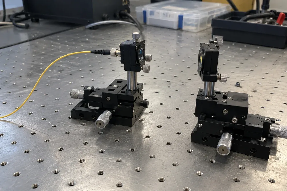
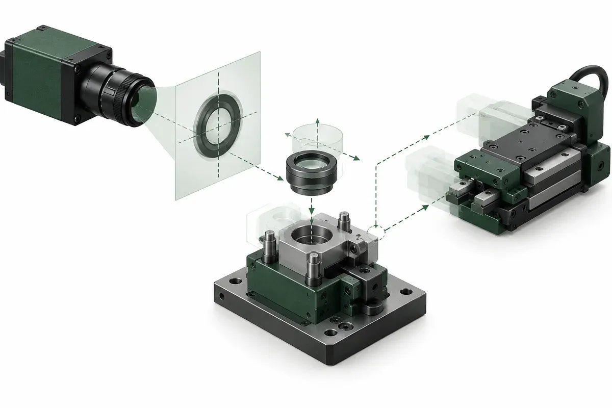
A vision-guided fixture converts a feature found in an image into a motion request. That conversion creates several opportunities for error before the stage reaches its destination. A useful engineering brief separates image interpretation, coordinate conversion and mechanical placement instead of assigning the entire placement requirement to one repeatability number.
The proposed worksheet below is for concept evaluation. It does not establish vision accuracy, optical coupling performance or production suitability of a catalogue mechanism.
Identify what the camera actually observes
Name the feature used as a placement reference: a fiducial, package edge, interface feature or other approved target. State whether it is directly visible and whether its relationship to the functional optical interface is measured, specified or merely assumed.
Describe the relevant work plane and any expected height variation. The imaging engineer should decide whether the chosen optics and calibration adequately represent that variation. The motion brief should record the assumption and its verification method rather than declare a camera configuration universally suitable.
ficonTEC’s project page describes CALADAN as a vision-based fiber-array placement project. It is a third-party process reference, not a customer case for this catalogue and not proof of optical-power feedback in the proposed fixture.
Define the image-to-motion relationship
A pixel coordinate needs a defined relationship to the physical coordinate frame used by the controller. Document how that relationship is established, where it is valid and what reference artifact or method is used to check it.
Include the sign convention and orientation. A mirrored image or rotated camera view can produce a plausible-looking but incorrect movement if conventions are left implicit. Ask for a verification record that checks multiple positions in the intended working area, rather than only demonstrating agreement at one central point.
Decide whether the camera moves with the assembly or remains fixed. Moving it changes the relevant cable and mounting requirements and may change which parts of the transformation remain constant. Record the chosen architecture on the fixture drawing.
Allocate error without double counting
Keep separate lines for feature localization, calibration residuals, mechanical movement, part location in its holder and any change after placement. These are categories for investigation, not numbers to add casually. The engineering reviewer should choose a defensible combination method after understanding which effects are systematic, variable or related.
Define the final measurement at the functional interface. A controller reaching its target coordinate and a camera seeing its reference feature do not necessarily prove that the interface itself is within the desired tolerance. If that relationship cannot yet be measured, identify it as a validation gap.
Practical vision-fixture checklist
- Name the visible reference feature and its relationship to the functional interface.
- Show the camera frame, motion frame and relevant work plane on one drawing.
- Record the calibration method, valid area and reference configuration.
- Specify what happens when the feature is missing, ambiguous or partly hidden.
- Record each error contributor and who will supply its evidence.
- Define a final placement check independent of the requested motor coordinate.
- Identify changes that trigger recalibration or a fresh verification.
Retain images associated with rejected placements when permitted by the process. They help distinguish an identification failure from a mechanical positioning problem and give the next design review more than a single pass percentage.
Hypothetical example: a fixture spacer changes the result
Imagine a concept bench calibrated with a reference plate at one height. A later adapter raises the optical package, while the software continues using the original image-to-motion relationship. The stage may execute exactly the same coordinate commands, but that does not prove that the old calibration remains applicable.
The team records the new adapter revision, checks the working plane and repeats its placement verification using the actual configuration. This example predicts no error magnitude. Its point is that a mechanical change can invalidate an imaging assumption without changing the stage’s catalogue specification.
Request evidence at the right boundary
Ask the stage supplier for the motion and interface evidence it can actually provide. Ask the vision integrator for calibration and feature-detection evidence. Ask the assembly team for final placement results under representative loading and part variation. Use multi-axis listings to compare mechanical layouts, then close each remaining evidence gap through a defined evaluation. No single supplier’s component rating should silently become a complete vision-system guarantee.
Questions
Does camera pixel size equal placement accuracy?
No. Optical geometry, calibration, feature localization, motion and fixture behavior all affect the final placement.
Can a vision reference be called active optical alignment?
Not solely because it guides motion. State whether feedback comes from images or a measured coupling signal.
When should calibration be reconsidered?
After changes that can alter the image-to-motion relationship, including optics, camera pose, fixture mounting or the relevant work plane.
Sources & scope
Sources support the specific points described below. General engineering guidance and third-party examples do not establish a catalogue model's performance or suitability.
- ficonTEC: Projects and Initiatives
CALADAN is a third-party vision-based fiber-array placement example, distinct from optical-power feedback.
Accessed
Related engineering resources
Continue reading
Applications & System Design
Building a positioning brief for an optical-power search experiment
Define a bounded optical-power search experiment with measurement validity, pose association and stop criteria before specifying motion hardware.
Application guide · 4 min read ·
Applications & System Design
Field-of-view calculator and calibration for stage motion
Use the field-of-view calculator for camera and microscope coverage, check calibration and turn the usable field into a stage-motion brief.
Application guide · 8 min read ·From requirements to a quotation
Review your stage requirements
Share the motion envelope, payload, orientation and acceptance criteria. Request confirmation of the exact configuration before ordering.
Request a Quote