Key takeaways
- A bearing, a guideway and a complete stage have different evidence boundaries.
- Mass, force, moment and allowable load are separate quantities.
- Natural frequency, resonance, damping and isolation describe different behavior.
- Use a thermal coefficient only with its material and temperature basis.
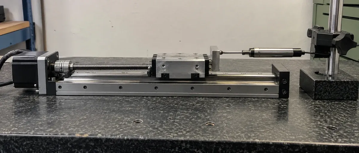
A stage review often uses familiar words for different physical objects. A bearing supports motion; a stage is an assembly. Mass is not force, a payload rating is not a moment limit, and a temperature record is not a thermal-error prediction. The distinctions below supply definitions and bounded calculations that can be attached to a positioning requirement. They establish no material grade, allowable load or measured performance for a catalogue model.
Linear bearings, guideways and complete stages
A linear bearing supports relative movement along a straight path while carrying specified loads. In a plain linear bearing, surfaces slide against one another without rolling elements. A rolling linear bearing uses balls or rollers between moving and supporting surfaces. Recirculating designs return the rolling elements through a circuit; other designs retain them in a finite-travel arrangement. NSK’s component explanation describes these distinctions. They are mechanisms, not universal rankings of accuracy or service life.
A guideway is the guiding arrangement: the mating rail or track, bearing/carriage and associated geometry that constrain unwanted movement. A complete positioning stage combines guidance with its structure, moving interface and drive. Reference sensors, feedback and a controller package must be identified separately; their inclusion is not implied by the bearing name.
Thus “linear-ball guideway” does not specify the finished stage’s stiffness, preload, straightness or workpiece accuracy. A plain bearing is not automatically unsuitable, and rolling elements do not automatically make an assembly precise. Compare the actual stage and its test basis, not a component label detached from its mounting and load.
Separate mass, force and moment
Mass, expressed in kilograms, characterizes inertia. Force, expressed in newtons, is a directional interaction. One newton is one kg·m/s². The NIST SI reference separates these units; a numerical kilogram entry is not already a force value.
For gravity loading, F_g = m g. With a hypothetical carried mass of 1.5 kg and an assumed g = 9.81 m/s², the weight magnitude is 14.715 N. Its axial and transverse components depend on installation orientation. Contact, cable and acceleration forces remain additional contributions.
A moment describes a force’s turning effect about a reference: in a simple perpendicular case, M = F r, using distance r in metres. If that illustrative weight acts with a 60 mm perpendicular lever arm, the moment magnitude is 14.715 × 0.060 = 0.8829 N·m. This is an input calculation, not an allowable moment. A force through the reference can have zero moment there while still loading the support. Drive torque and a bearing’s permitted overturning moment also require separate definitions despite sharing N·m units.
Read a load rating at its stated boundary
A payload rating refers to a defined product and set of conditions. Ask whether it concerns centred or offset loading, the relevant directions, orientation, stationary or moving operation, and the complete supplied assembly. Do not invent an unstated basis. Zaber’s rotary selection guide demonstrates how installation orientation changes loading categories; its ratings are not ours.
The lower axis of a stack carries the upper mechanism as well as the workpiece. Report that carried group, its centre of mass and external forces at relevant positions. A bearing-component capacity does not automatically rate its mounting plate, drive, joints or finished stage. Likewise, multiplying a catalogue mass by gravity does not create permission for the resulting force in every direction.
Natural frequency is a property of a defined system
Natural frequency describes a mode of free vibration. An ideal undamped, single-degree-of-freedom mass–spring model has
f_n = (1 / 2π) √(k / m),
where k is stiffness in N/m, m is mass in kg, and f_n is in hertz. This follows the harmonic-oscillator model discussed in The Physics of Waves, hosted by MIT OpenCourseWare.
For invented model inputs k = 80,000 N/m and m = 2 kg, f_n is approximately 31.8 Hz. More mass lowers this model’s frequency; more stiffness raises it. A real stage, bracket, payload and base have several coupled modes. The example is not a catalogue resonance value, and replacing a holder can change the relevant system even when the stage part number stays the same.
Resonance and a vibrating stepper
Resonance is a strong forced response associated with a mode when excitation occurs near the relevant frequency. The peak depends on damping and the response being observed; a measured peak is not automatically identical to an undamped natural-frequency calculation.
Stepper motion supplies repeated excitation. Rotor inertia and electromagnetic restoring stiffness can participate in oscillation, while the transmission and fixture add mechanical modes. Dover Motion’s stepper handbook explains this mechanism and its possible relation to noise, vibration and lost synchronism. Its example frequencies and drive arrangements do not identify a resonance band for another motor or loaded stage.
A useful diagnosis starts with the symptom: does vibration occur while holding, within a repeatable speed region, after stopping, or when nearby equipment runs? Preserve the approved profile, motor/drive identities, load, mounting and position evidence. A repeatable speed-dependent peak is consistent with resonance, but is not proof of its cause. Compare time/frequency observations at the process point with controller information. Have the responsible provider check documented drive/configuration and mechanical conditions before changing them. Neither a command counter nor the sound alone establishes missed steps. Do not create a diagnostic test by obstructing the axis or guessing current, preload or recovery settings.
Damping and isolation solve different problems
Damping dissipates vibration energy. After excitation ends, it affects ring-down; under continuing excitation it affects the response rather than making every displacement vanish. Vibration isolation reduces transmission between a disturbance source and the supported equipment. It does not mean simply adding mass, making a base level or waiting after a commanded move.
Newport’s vibration fundamentals distinguishes these mechanisms. A compliant passive support introduces its own loaded dynamics and can amplify motion near resonance before providing attenuation in a suitable frequency region. Consequently, “softer is better” is not a general selection rule. Identify disturbance frequencies, supported mass, support modes and motion at the functional point. Isolation of floor disturbance is also separate from settling of a stage-generated move. This reference selects no isolator or acceptable vibration level for an installation.
Thermal expansion coefficient and thermal movement
The linear coefficient of thermal expansion, α, describes fractional length change per temperature change. It is expressed in K⁻¹, often as µm/(m·K). A temperature difference of 1°C equals a difference of 1 K; absolute Celsius and kelvin temperatures are not interchangeable.
For uniform temperature and an appropriate constant or interval-average coefficient, the free-length estimate is ΔL = α L₀ ΔT. Match α to the alloy/product condition and temperature interval. Over a wider range, temperature dependence may require an appropriate expansion relation rather than one constant.
There is no universal coefficient for everything labelled aluminium. Kaiser’s extruded-alloy technical data, on its 6061 physical-properties page, lists typical linear expansion of 23.6 µm/(m·K) over 20–100°C. That is a material reference with an interval, not a measured property of any listed stage or a guaranteed coefficient for an unidentified alloy.
A bounded thermal calculation
Consider an illustrative, uniformly heated, unconstrained 6061 length with L₀ = 100 mm at 20°C. Use that reference coefficient over the same 20–100°C interval, so ΔT = 80 K:
ΔL = 23.6 × 10⁻⁶ K⁻¹ × 100 mm × 80 K = 0.1888 mm = 188.8 µm.
The interval is chosen to match the source table, not to prescribe a stage operating temperature. The calculation concerns free material length. Constraints, dissimilar supports and temperature gradients can produce other deformations; the sensor reference may also move. Do not label the result positioning error or subtract it as a proven compensation value.
For a real test, record material evidence, initial reference length, temperatures and locations, time history, load and the independently observed functional point. Use the specification basis to keep estimated contributions separate from measured assembly results. These definitions make the next calculation or supplier question precise; they do not replace configuration-specific evidence.
Questions
What is a linear bearing, and is it a complete stage?
It supports guided relative motion along a straight path under specified loading. A complete stage also combines structure, moving interface and drive; bearing terminology alone does not specify the assembly or its performance.
Can a payload in kilograms be converted into an allowable force or moment?
Mass can be used to calculate an assumed gravitational force, and geometry can give its moment. Those calculations do not establish an allowable rating in a different direction or configuration.
Does a vibrating stepper prove resonance?
No. Resonance is a possible mechanism, but observed vibration needs its speed/holding/settling conditions and measurement evidence. The motor, drive, fixture, services and external disturbance can contribute; use documented checks rather than guessing settings.
What thermal expansion coefficient should I use for aluminium?
Identify the alloy/product condition and temperature interval. This guide gives a typical extruded-6061 reference of 23.6 µm/(m·K) over 20–100°C, not a universal aluminium constant or a property of a catalogue stage.
Does vibration isolation remove the need to verify settling?
No. Reducing transmitted disturbance and evaluating the response to a commanded stage move are separate tasks. A passive support can also amplify motion near its loaded resonance.
Sources & scope
Sources support the specific points described below. General engineering guidance and third-party examples do not establish a catalogue model's performance or suitability.
- NSK: Linear Ball Bearings
Linear-bearing function and plain versus rolling-element arrangements; no component rating is transferred.
Accessed - NIST Guide to the SI, Chapter 4
Mass, force and moment units, and equality of Celsius/kelvin temperature intervals; worked load arithmetic is original.
Accessed - Zaber: Selecting a Motorized Rotary Stage
Installation orientation and axial/radial/moment loading categories; no Zaber capacity is copied.
Accessed - MIT OpenCourseWare: The Physics of Waves
Ideal harmonic-oscillator and damped/forced-response concepts; the 31.8 Hz model example is hypothetical.
Accessed - Dover Motion: Stepper Motors
Rotor stiffness/inertia resonance and possible vibration/lost synchronism; handbook frequencies and settings are not adopted.
Accessed - Newport: Fundamentals of Vibration Control
Mass/compliance, damping and vibration-transmission/isolation distinctions; no isolator or installation is qualified.
Accessed - Kaiser Aluminum: Extruded Standard Shapes Technical Data
Typical 6061 linear expansion 23.6 µm/(m·K), stated interval 20–100°C; no catalogue alloy or guaranteed stage property is inferred.
Accessed
Related engineering resources
Continue reading
Accuracy & Metrology
Accuracy, repeatability and resolution: three separate acceptance questions
Turn accuracy, repeatability and resolution into separate acceptance requirements, with a worksheet for evidence, conditions and decisions.
Verification guide · 4 min read ·Accuracy & Metrology
Assessing velocity stability and following error during a scan
Plan scan-motion measurements with explicit trajectory definitions, acquisition bandwidth, payload and processing for velocity and following error.
Verification guide · 4 min read ·From requirements to a quotation
Review your stage requirements
Share the motion envelope, payload, orientation and acceptance criteria. Request confirmation of the exact configuration before ordering.
Request a Quote