Key takeaways
- Use calibrated sample-plane field of view to plan tile positions.
- Tile overlap, travel and stitching quality are different requirements.
- Include sample-holder access and focus variation in the scan review.
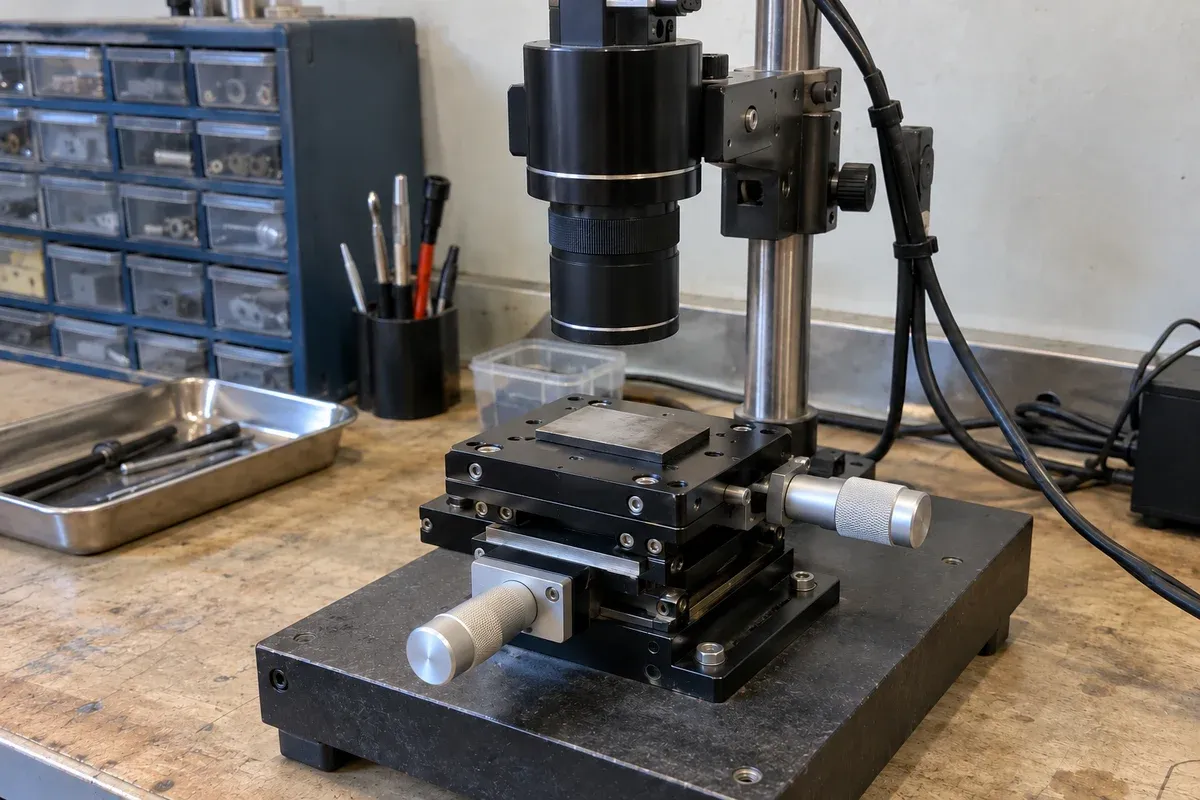
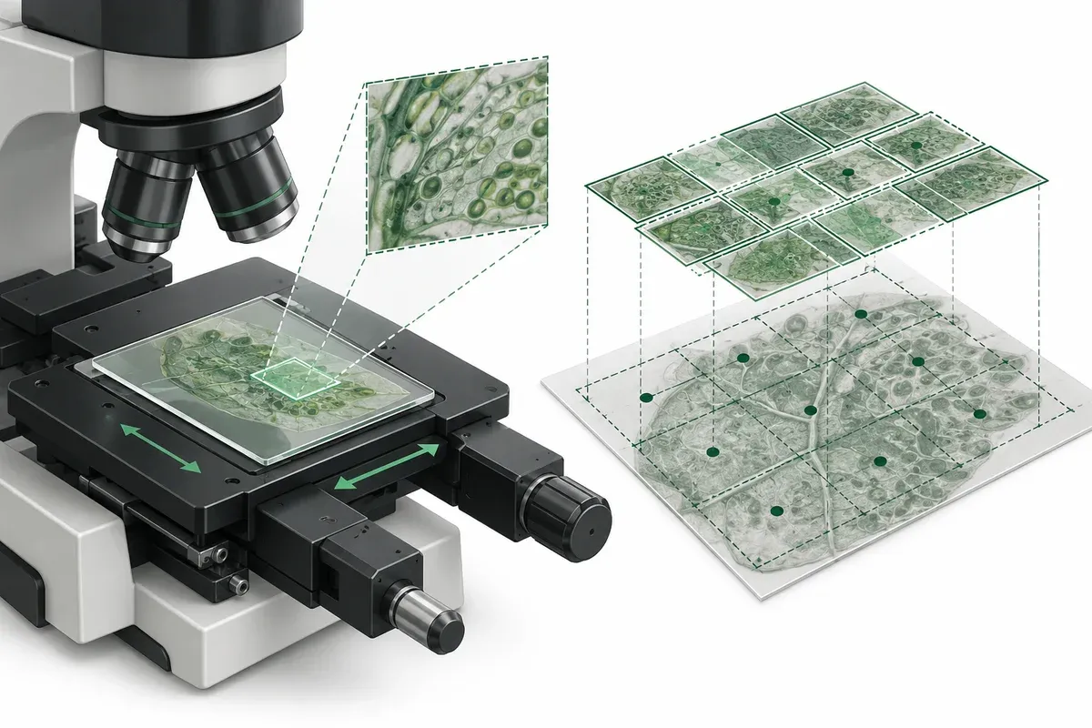
An image mosaic covers an area larger than one camera view by collecting multiple fields. The XY motion requirement follows from where those views must be centered, while successful stitching depends on additional imaging and software conditions. Keeping these two questions separate prevents a visually appealing mosaic from becoming unsupported evidence of stage accuracy.
This article describes a conceptual scan-planning exercise. It does not claim microscope compatibility, medical suitability or validated imaging performance for a catalogue stage.
Establish field of view at the sample
Ask the imaging engineer for the calibrated width and height of the usable field in the sample plane. The camera’s pixel count alone is insufficient: the optical configuration determines how pixels correspond to the specimen.
Micro-Manager’s Slide Explorer documentation explicitly connects correct tile positioning with calibration of pixel size and orientation. Use that principle to require a calibration record for the intended camera and optics. It does not establish that a particular catalogue controller supports that software.
Document any crop or excluded image border. If the acquisition retains only a central region, planning with the full sensor dimensions can leave unobserved gaps. Preserve the camera orientation on the same sketch as the stage coordinate directions.
Calculate tile-center spacing
For a chosen fractional overlap, the nominal step is the usable field dimension multiplied by one minus that fraction. Treat this as planning geometry, not proof that the selected overlap is sufficient for a particular stitching algorithm.
Along one direction, coverage from evenly spaced tiles is one field width plus the number of intervals multiplied by the step. The corresponding center-to-center motion span omits the initial field width. This distinction helps prevent unnecessary travel requirements or an accidental reduction in coverage.
MicroMagellan’s documentation treats overlap and Z-step size as acquisition choices. The experiment owner should decide both from the sample and reconstruction needs rather than copy a default into the motion specification.
Include focus, holding and acquisition time
An XY scan may cross a sample that is not flat relative to the imaging plane. Decide whether a fixed focus, sampled focus map or another validated method will be used. Record the assumption without promising that XY motion alone maintains image sharpness.
Show the sample holder, clamps and objective clearance at all tile locations. A scan area fitting within nominal travel does not prove that the holder fits beneath the optical assembly. Also include the loading position if it requires movement beyond the image-acquisition region.
For timing, distinguish movement, settling or readiness confirmation, exposure and data handling. Maximum stage speed is not mosaic throughput. Request a representative acquisition trial if overall duration matters to the application.
Scan-brief worksheet
Complete this worksheet before turning an image-area request into a travel requirement. Assign a named owner to each unresolved item so that an unknown acquisition setting does not silently become a motion requirement.
| Brief item | Record for this scan |
|---|---|
| Region and coordinates | Required sample-plane boundary; coordinate origin, units and positive X/Y directions; any loading position outside that boundary. |
| Usable field and crop | Calibrated usable width and height at the sample; retained pixel crop and excluded borders; camera, optics and calibration record used. |
| Overlap by axis | Proposed X and Y overlap separately, resulting center steps, and who will validate overlap with representative images. |
| Pixel orientation | Calibrated mapping of image columns/rows to sample X/Y, including signs; a recognizable feature used to check axis swaps or reversal. |
| Focus and clearances | Focus method and acceptance check; holder, clamp, objective and cable clearances at corners and the loading position. |
| Acquisition responsibilities | Who confirms readiness, authorizes exposure and checks the saved image; the condition used for each handoff. |
| Dataset and recovery | Who logs tile ID, row/column, target coordinates, any available position readback, timestamps, filename and complete/failed/skipped status; retry and exclusion rules. |
Use a small test region with recognizable features to check ordering and orientation before relying on a large coordinate list. Identify the first tile of each row and state whether alternate rows reverse direction. A reversed traversal order and a reversed coordinate axis are different choices; retain the physical tile coordinates even when the acquisition order changes.
Hypothetical example: six fields across a strip
Suppose an illustrative rectangular sample region is 10 mm wide, the calibrated usable field is 2 mm wide and the proposed overlap is 20 percent. The step is 1.6 mm. Six fields cover 2 mm plus five intervals of 1.6 mm, or 10 mm. Their center-to-center span is 8 mm.
Set the left edge of the required region to X = 0 mm and place the first center half a usable field inside it. The centers are 1.0, 2.6, 4.2, 5.8, 7.4 and 9.0 mm. With a half-field of 1.0 mm, their respective usable intervals are 0.0–2.0, 1.6–3.6, 3.2–5.2, 4.8–6.8, 6.4–8.4 and 8.0–10.0 mm. Adjacent intervals overlap by 0.4 mm, and their union covers 0–10 mm; the center span is 9.0 − 1.0 = 8.0 mm. These are coordinates relative to the chosen sample-region origin; a separate, checked coordinate mapping is needed for an actual setup.
These values are invented solely to explain coverage arithmetic. They are not stage specifications, a recommended overlap or a claim that six images will stitch successfully. The second direction needs its own calculation, and additional handling travel must be considered separately.
Verify coordinates, coverage and reconstruction separately
A valid coordinate list, complete image coverage and an acceptable reconstruction answer different questions. Record evidence for each rather than treating a successful stitch as a substitute for the other checks.
| Check | Evidence to retain | If it fails |
|---|---|---|
| Coordinates and order | Tile IDs with intended sample coordinates; a small feature-based orientation test identifying positive X/Y and the first tile of each row. Compare any available recorded positions separately from targets. | Check origin, units, swapped axes and sign or row-order reversal before extending the scan. Do not rename tiles to hide a coordinate mismatch. |
| Usable coverage | Label target-center field-footprint overlays as planned coverage; mark missing or invalid images as holes. For observed coverage, retain acquired-image boundaries mapped by the calibration, plus evidence appropriate to the analysis task from adjacent-image overlap/features and/or independent position measurements. Complete tile files alone leave unverified extent unconfirmed. | Recalculate planned coverage if the crop or grid changes. Obtain or check observed-coverage evidence separately; reacquire, explicitly exclude or leave unconfirmed regions without adequate evidence. |
| Image and stitching validity | Representative focus, exposure and overlap checks; reconstruction assessed against the intended analysis requirement. | Have the imaging owner review calibration, focus, image content and reconstruction settings. Correct geometry alone cannot guarantee a valid stitch. |
| Interrupted or incomplete tile | Tile ID, attempt number, last confirmed acquisition state, error and whether a usable file was saved. Keep retry files linked to the original tile. | Mark uncertain, failed or skipped tiles explicitly; let the acquisition owner select a checked restart point. Do not silently count an incomplete tile as complete. |
Use multi-axis stage listings for a preliminary geometry comparison, followed by exact interface and controller confirmation. Neither a correct tile count nor a catalogue repeatability value qualifies the full imaging workflow.
Questions
Is travel equal to the sample width?
Not necessarily. The required travel is the span between selected tile centers plus any separately justified approach or handling movement.
Does a small stage repeatability guarantee seamless stitching?
No. Calibration, image content, illumination and the stitching method also require verification.
Can the catalogue stages be assumed compatible with Micro-Manager?
No. These sources describe acquisition planning. Compatibility of the exact motion controller, device adapter and software version must be confirmed separately.
Sources & scope
Sources support the specific points described below. General engineering guidance and third-party examples do not establish a catalogue model's performance or suitability.
- Micro-Manager: Slide Explorer Plugin
Primary software documentation identifies pixel size and orientation calibration as necessary to position image tiles.
Accessed - Micro-Manager: MicroMagellan
Documents image tile overlap and Z-step choices in microscope acquisition; does not establish catalogue compatibility.
Accessed
Related engineering resources
Continue reading
Applications & System Design
Field-of-view calculator and calibration for stage motion
Use the field-of-view calculator for camera and microscope coverage, check calibration and turn the usable field into a stage-motion brief.
Application guide · 8 min read ·
Applications & System Design
Defining a rotary indexing sequence for camera-based part inspection
Build a rotary inspection brief around required camera views, part references, indexed stops and acquisition evidence, without assuming inspection yield.
Application guide · 4 min read ·From requirements to a quotation
Review your stage requirements
Share the motion envelope, payload, orientation and acceptance criteria. Request confirmation of the exact configuration before ordering.
Request a Quote