Key takeaways
- Name the coordinate frame before labeling angular errors.
- Record sensor and workpiece offsets when interpreting angular motion.
- Do not substitute a straightness trace for a complete angular measurement.
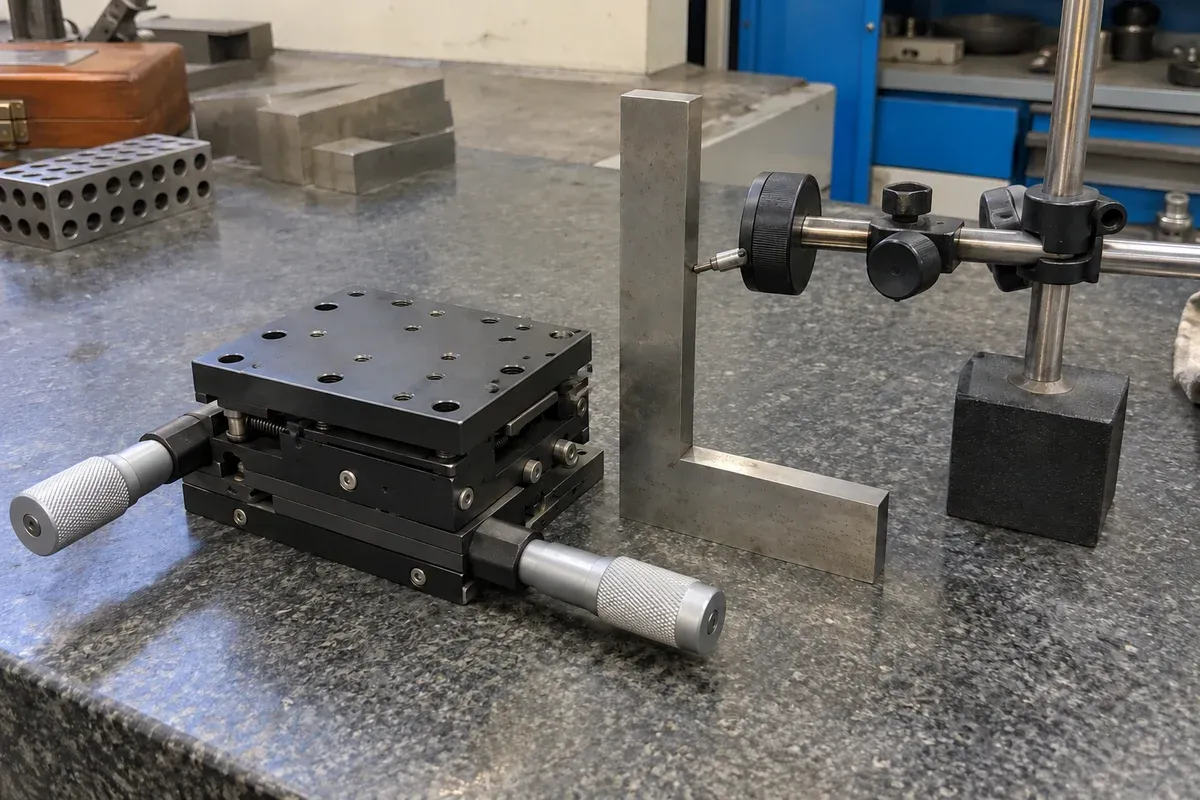
Draw the coordinate frame before choosing sensors
Pitch, yaw and roll are useful labels only when their axes are clear. Draw the direction of travel, the vertical direction and the positive rotation convention on the setup sheet. For a stage traveling along X, Newport identifies roll about X, pitch about Y and yaw about Z in its motion terminology reference.
Do not assume that a stage mounted vertically preserves a casual bench-top interpretation of those words. Attach the labels to the declared coordinate frame. A report should let another engineer reconstruct what rotated, relative to which reference, and where the measurement was made.
Match each measurement to its objective
First decide whether the application needs an angular specification, a displacement bound at the workpiece, or both. An optical beam may be sensitive to orientation, while a raised probe may be sensitive to the displacement caused by angular motion. These objectives can require different reference arrangements even when the same stage is being evaluated.
Select instrumentation and mounting geometry that make the desired component observable. An autocollimator with an appropriate reflector arrangement, angular interferometric optics, or a suitably designed differential displacement setup may be candidates. Suitability depends on range, uncertainty, alignment and access. Do not assume that one instrument arrangement measures every rotation component.
A single indicator reading against a surface can combine surface shape, translation, alignment and rotation. If that arrangement is used, document what it measures and what additional observations are needed to separate contributions. The practical question is not whether the trace looks smooth, but whether it supports the particular angular claim.
Keep geometry and processing visible
Record reflector location, probe separation, target height and reference-base location. Preserve the raw observations used to calculate angle. If a differential measurement is divided by a baseline length, include the baseline’s units and uncertainty. Avoid mixing millimeters, meters and angular units in a spreadsheet without an explicit conversion step.
Specify target positions, direction, load, dwell and whether the data are static or collected during motion. A dynamic trace and a sequence of settled observations may be useful for different purposes. Report the sampling and filtering used, and retain any fitted trend separately from the original data. Removing a slope may change the question the plotted result answers.
Connect the angular measurement back to the payload drawing. Zaber’s multi-axis accuracy guide discusses system geometry and assembly effects. Use that system-level perspective without treating a single-axis angular rating as a guarantee for a complete stacked mechanism. The mounting structure and functional-point offsets still need evaluation.
Hypothetical example: a raised inspection probe
Imagine a probe positioned above a linear carriage on a rigid spacer. The proposed test records pitch over the working region and separately observes the probe-tip position. No measured angle, displacement or acceptance threshold is assumed. The purpose is to determine whether the carriage-level measurement adequately represents the probe location.
If the spacer height is changed, the team revisits the geometry rather than reusing the old probe-tip conclusion. Even an unchanged angular trace can have a different positional consequence at a different point. Conversely, a satisfactory tip-position result in one direction does not prove that all three angular components meet an unstated requirement.
Practical checklist for angular-error measurements
- Draw the coordinate axes and positive rotation signs.
- State whether the requirement concerns angle, point displacement or both.
- Explain how the sensor arrangement isolates the intended component.
- Record offsets, baselines, target geometry and reference-base details.
- Preserve raw observations and disclose any trend removal or filtering.
- Separate static and dynamic measurement conditions.
- Reassess the application conclusion after changing payload geometry.
The final report should identify the measurement’s observability limits as clearly as its results. Link the underlying positioning terms to the specification guide rather than presenting pitch, yaw or roll as synonyms for accuracy. An angular measurement adds geometric evidence to the system model; it does not automatically establish command resolution, repeated-return performance or complete workpiece accuracy.
Questions
Is pitch always rotation about the same laboratory axis?
Only after the coordinate convention is specified. Define the travel and reference axes before assigning labels.
Can one indicator measure all three angular components?
Not generally. A single displacement reading can mix translation and rotation; the measurement geometry must make the desired component observable.
Why does workpiece height matter?
Angular motion changes the position of points away from the rotation reference. Record the offset when evaluating the application effect.
Sources & scope
Sources support the specific points described below. General engineering guidance and third-party examples do not establish a catalogue model's performance or suitability.
- Newport: Motion Basics Terminology and Standards
For X-axis travel, roll is about X, pitch about Y and yaw about Z.
Accessed - Zaber: Multi-Axis Accuracy Guide
Multi-axis accuracy requires considering geometry and assembly rather than only individual-axis ratings.
Accessed
Related engineering resources
Continue reading
Accuracy & Metrology
Accuracy, repeatability and resolution: three separate acceptance questions
Turn accuracy, repeatability and resolution into separate acceptance requirements, with a worksheet for evidence, conditions and decisions.
Verification guide · 4 min read ·Accuracy & Metrology
Assessing velocity stability and following error during a scan
Plan scan-motion measurements with explicit trajectory definitions, acquisition bandwidth, payload and processing for velocity and following error.
Verification guide · 4 min read ·From requirements to a quotation
Review your stage requirements
Share the motion envelope, payload, orientation and acceptance criteria. Request confirmation of the exact configuration before ordering.
Request a Quote