Key takeaways
- Squareness belongs to the assembled coordinate system.
- Separate a fitted angular relationship from local straightness variation.
- Preserve datum, loading and measurement-plane details before adjustment.
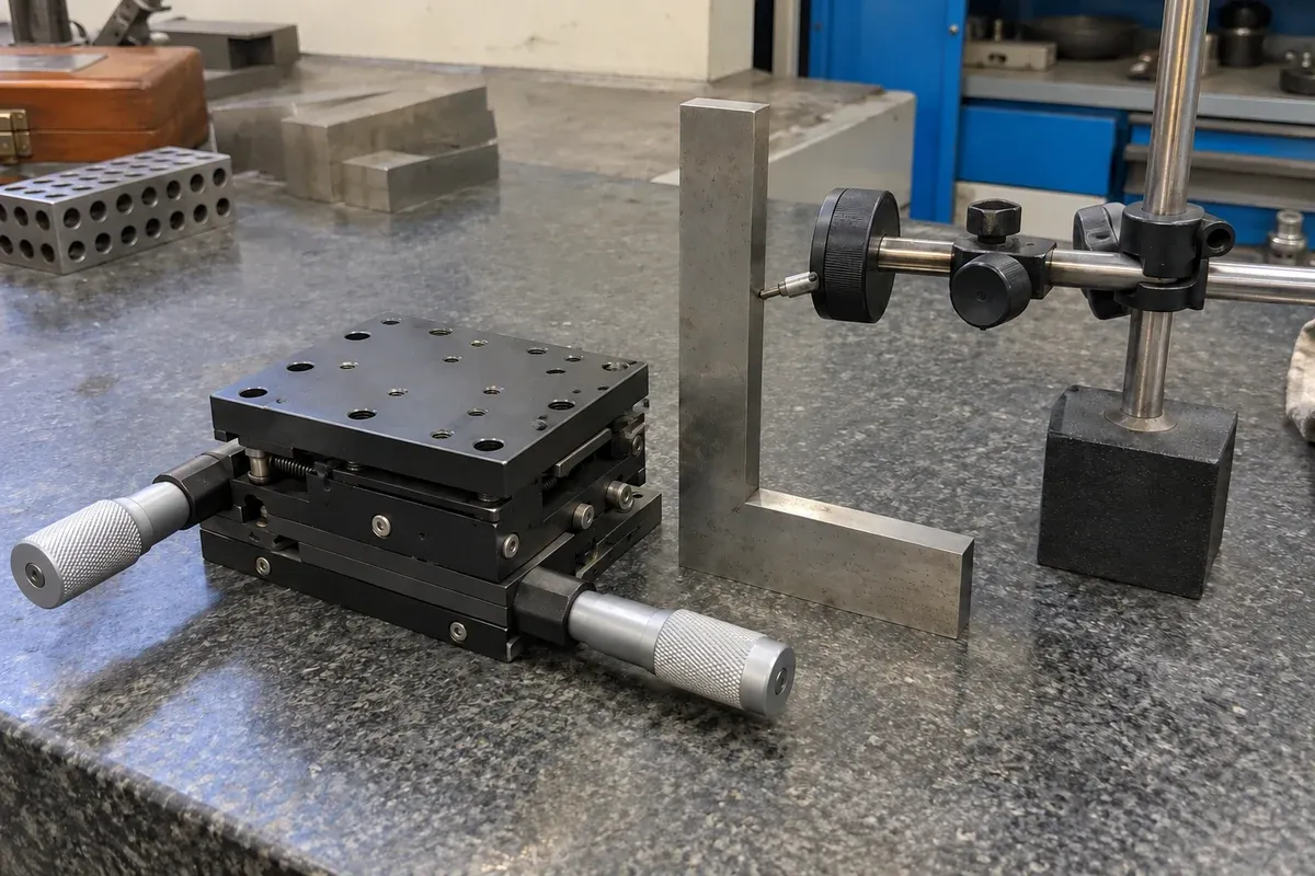
Define the assembly datum first
Squareness is a relationship between motions in an assembled system. It cannot be established simply by placing two individually accurate stages at nominal right angles. Before choosing a reference artifact, identify the coordinate frame that matters to the process: a baseplate feature, an optical axis, a fixture datum or another agreed reference.
Zaber’s multi-axis accuracy guide describes perpendicularity checks and the need to identify a global reference. Use that principle to write an assembly-specific plan. The objective is not to copy a supplier’s demonstration dimensions or assume its instruments will meet a different system’s requirement.
Choose a reference and measurement plane
Select a calibrated square, suitable optical arrangement or other reference method whose uncertainty is appropriate for the proposed requirement. Record the reference’s identity, usable faces, orientation and condition. A nominally square machined block without supporting evidence should not become an unquestioned angular standard.
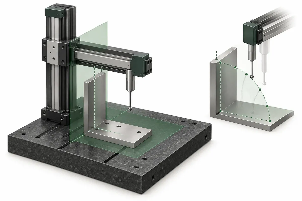
Specify the plane and height at which the measurement occurs. The workpiece may sit above the moving carriage, and a stacked arrangement can change geometry with payload position. Include the complete installed load or explain how the test load differs. Record cable and hose routing when those attachments are part of the operating setup.
Document how the first axis is related to the reference and how the second axis is evaluated without losing that relationship. If a probe or reference must be remounted, include a check that the original alignment has not shifted. A convenient physical arrangement is not sufficient unless the measurement chain remains understandable.
Sample enough geometry to interpret the result
Collect observations along the relevant travel rather than relying only on two endpoint readings. A fitted slope can describe an overall angular relationship, while local departures from that fit indicate path variation within the measurement. Retain both. Removing the fitted slope from a plot does not make the assembly square; it changes the plotted quantity.
Repeat the measurement with controlled approach directions and record timestamps. If possible, include independent checks that help separate reference-artifact error, probe mounting and axis behavior. The exact reversal or substitution method needs a measurement specialist’s review; it should not be improvised merely because the first trace is inconvenient.
For larger working areas, consider whether measurements at one cross-section are enough. A stacked carriage may behave differently at another position of the supporting axis. State the sampled coordinates and avoid generalizing a local result to the complete working volume. A full volumetric verification is a broader task than one perpendicularity measurement.
Hypothetical example: an XY inspection fixture
Imagine an XY fixture aligned to a machined datum on its baseplate. The engineer proposes a square-reference check near the center of the working area and additional measurements with the lower axis at two other relevant positions. No actual error, instrument capability or acceptance threshold is assumed.
The first pass is retained before any adjustment. After the assembly is realigned, the same sequence is repeated with the payload installed and the reference relationship checked again. A better central slope is useful evidence, but the report also inspects local path variation and the other sampled positions. It does not declare the entire machine accurate based on a single favorable line.
Practical checklist for assembled squareness
- Identify the process datum and coordinate frame before aligning axes.
- Record the reference artifact, calibration information and measurement plane.
- Preserve alignment checks across probe or artifact remounting.
- Keep fitted angular relationships separate from local path residuals.
- Sample relevant positions of supporting and stacked axes.
- Retain before-and-after data when adjustments are made.
- State the uncertainty and geographic scope of the conclusion.
Use NIST’s reporting guidance when expressing uncertainty and its basis. The site’s specification guide explains why positioning accuracy, repeatability and resolution must remain separate. Squareness verification adds assembly geometry to that evidence; it does not make the individual values interchangeable or guarantee an unmeasured functional point elsewhere in the workspace.
Questions
Can two accurate single-axis stages form an inaccurate XY assembly?
Yes. Their assembled geometric relationship requires separate evidence; individual positioning ratings do not establish squareness.
Does a constant indicator reading prove the whole working area is square?
Only within the limits of the reference, setup, sampled path and measurement plane. State the scope and uncertainty.
Should squareness be measured before or after payload installation?
An unloaded alignment check can be useful, but application verification should represent the relevant installed configuration and loading.
Sources & scope
Sources support the specific points described below. General engineering guidance and third-party examples do not establish a catalogue model's performance or suitability.
- Zaber: Multi-Axis Accuracy Guide
Zaber describes perpendicularity verification using reference geometry and a declared global reference.
Accessed - NIST TN 1297: Reporting Uncertainty
Measurement uncertainty should be reported with its basis.
Accessed
Related engineering resources
Continue reading
Accuracy & Metrology
Accuracy, repeatability and resolution: three separate acceptance questions
Turn accuracy, repeatability and resolution into separate acceptance requirements, with a worksheet for evidence, conditions and decisions.
Verification guide · 4 min read ·Accuracy & Metrology
Assessing velocity stability and following error during a scan
Plan scan-motion measurements with explicit trajectory definitions, acquisition bandwidth, payload and processing for velocity and following error.
Verification guide · 4 min read ·From requirements to a quotation
Review your stage requirements
Share the motion envelope, payload, orientation and acceptance criteria. Request confirmation of the exact configuration before ordering.
Request a Quote